ASDA Series Application Note Introduction of E-Cam Operation
March, 2015 2-5
2.2 Source of the Master Axis
SXYZ
U
BA
0
0~30~50~20~800~3F-0~2
Low WordHigh Word
SXYZ
U
BA
0
0~60~20~800~3F-0~2
Low WordHigh Word
P5-88
Parameter settings
of E-Cam
Figure 2.4 P5-88.Y: Settings for Source of the Master Axis
Source of the master axis can be specified by P5-88.Y. Any pulses that conform to the hardware
specifications of ASDA-A2 can be the source of master axis, such as encoder, PLC, or a servo
drive. 7 sources are available on ASDA-A2:
P5-88.Y = 0: CAP axis (Capture axis); use the source of capture function (P5-39.Y) as the source
of master axis.
P5.88.Y = 1: AUX ENC (Auxiliary encoder); source signal of master axis is input via CN5
connected to an external encoder.
P5.88.Y = 2: Pulse Cmd (Pulse Command); pulse signal of the master axis is input from CN1.
P5.88.Y = 3: PR command; it is a virtual axis that acquires the internal signal. The PR specifies
the motion command and when this PR is carried out, the signal generated will be
regarded as the source of master axis.
P5.88.Y = 4: Time axis; the system generates signals every 1 ms and send them directly to the
master axis.
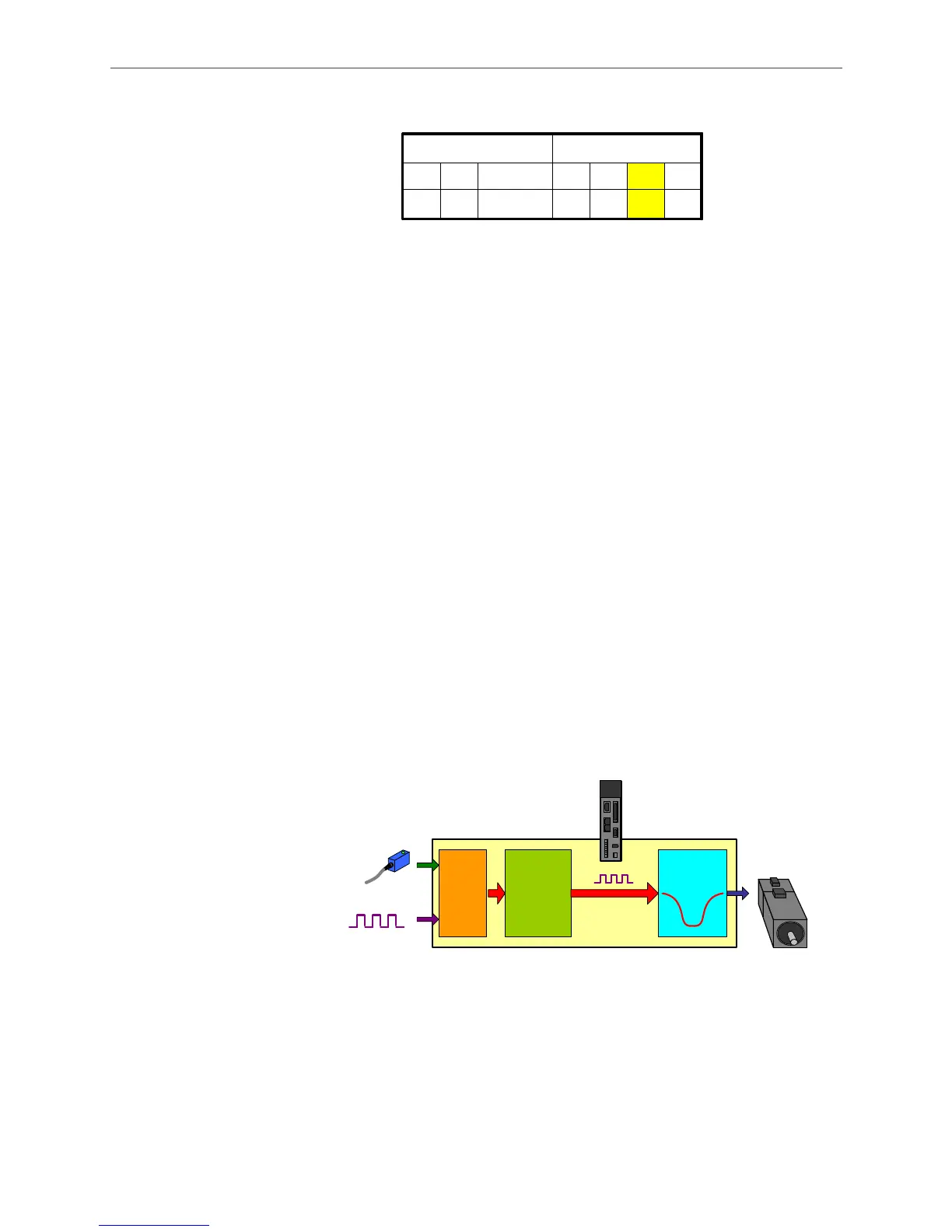
P5.88.Y = 5: Synchronous capture axis; signals from this axis have been adjusted. This is mainly
applied in the application of flying shears. This mechanism is to regard the
captured source signal that being corrected as the source signal for slave axis. In
the application of flying shears, if using mark-tracking function to correct its cutting
position, synchronous capture axis shall be specified as the source for the master
axis.
Figure 2.5 Synchronous Capture Axis
P5.88.X = 6: Analog channel 1; it is a virtual axis, which captures the analog voltage (via speed
channel by analog command) and regard it as the source of master axis. The unit
is the output frequency 1 M pulse/s corresponded by every 10 V.
DI7
CN1 or
CN5
Marking Sensor
Master source, P5-37,
set by Capture
parameter P5-39.Y.
(Y=1 or 2)
Correcting
Machanism
P5-78
P5-79
P5-80
Synchronous
Cap. axis
P5-77
Output
Servo
Drive
E-Cam
Curve

 Loading...


