ASDA Series Application Note Application Examples
March, 2015 3-69
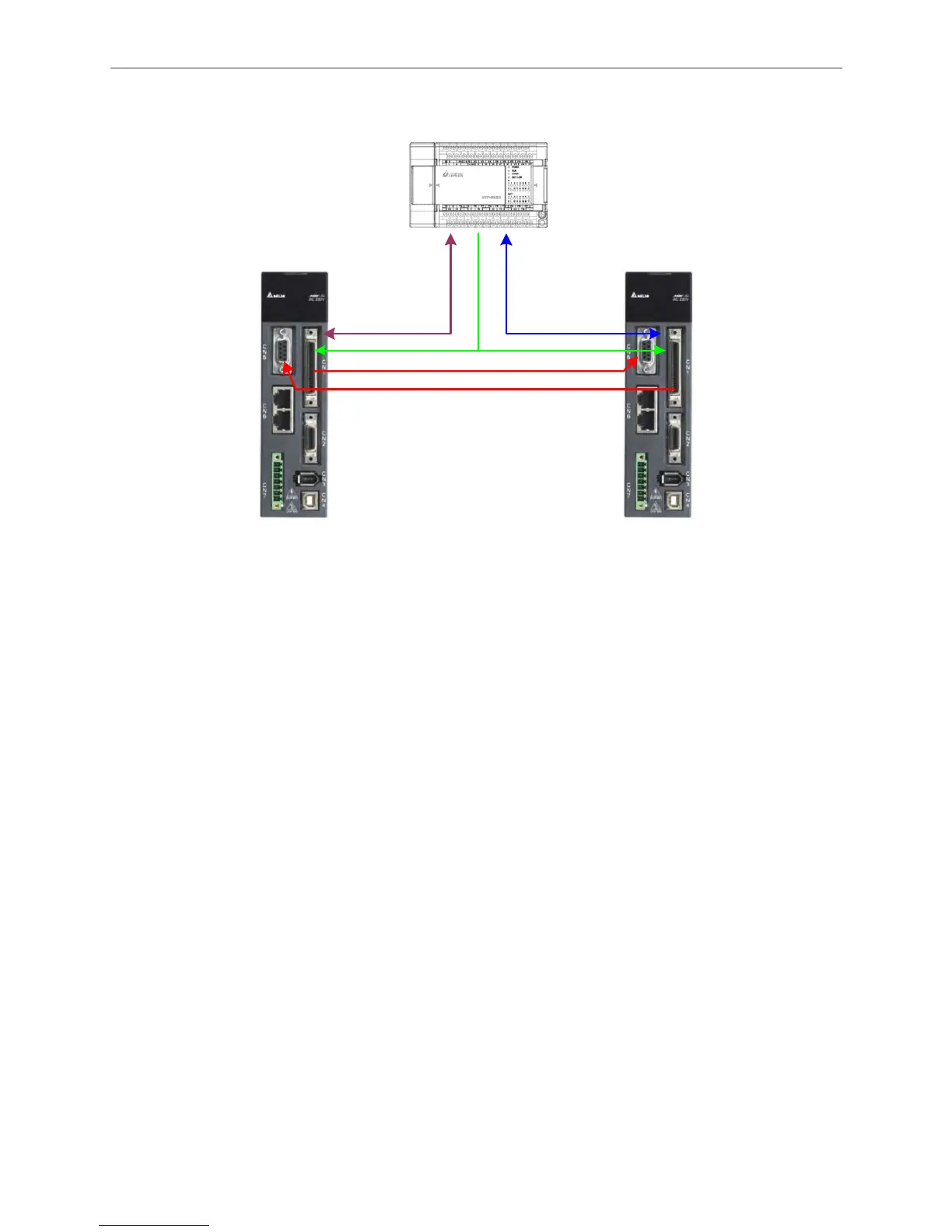
Host Controller
Axis 1
Axis 2
(1) DI/O signal used for communicating between
Axis 1 and the host controller
(2) DI/O signal used for communicating between
Axis 2 and the host controller
(3) Position command to Axis 1 and 2 sent by the
host controller
(4) Position pulse reference command to Axis 2
sent by from Axis 1
(5) Position pulse reference command to Axis 1
sent by Axis 2
(1) (2)
(3)
(4)
(5)
Figure 3.5.5 System Wiring Diagram
c. Pulse signal of position command
The pulse signal of host controller is directly parallel-connected and fed to both axes
simultaneously. If using open collector, please carefully apply the wire and the power to avoid
short circuit. ASDA-A2 supports three types of pulses; please refer to the manual for further
information. If Z pulse is regarded as the homing origin, Z pulse from one of the axes should be
sent back to the host controller.
d. The pulse signal communication between two axes
On Axis 1, CN1 will send pulse signals OA, /OA, OB, and /OB to OptA, /OptA, OptB, and /OptB of
CN5 on Axis 2. Same as this wiring, on Axis 2, pulse signals OA, /OA, OB, and /OB from CN1
has to be sent back to CN5 of Axis 1, receiving by OptA, /OptA, OptB, and /OptB. This wiring is
specially designed for the gantry, be sure to correctly connect them.
e. A detailed reference for wiring
Figure 3.5.6 is the detailed wiring reference. Users may take this reference to amplify or reduce
the signal. This reference is for the wiring of servo system only. Direct signal input to the host
controller such as position sensor is not included in this diagram. Be sure to reserve the DI/DO
port on host controller.

 Loading...


