ASDA Series Application Note Application Examples
March, 2015 3-105
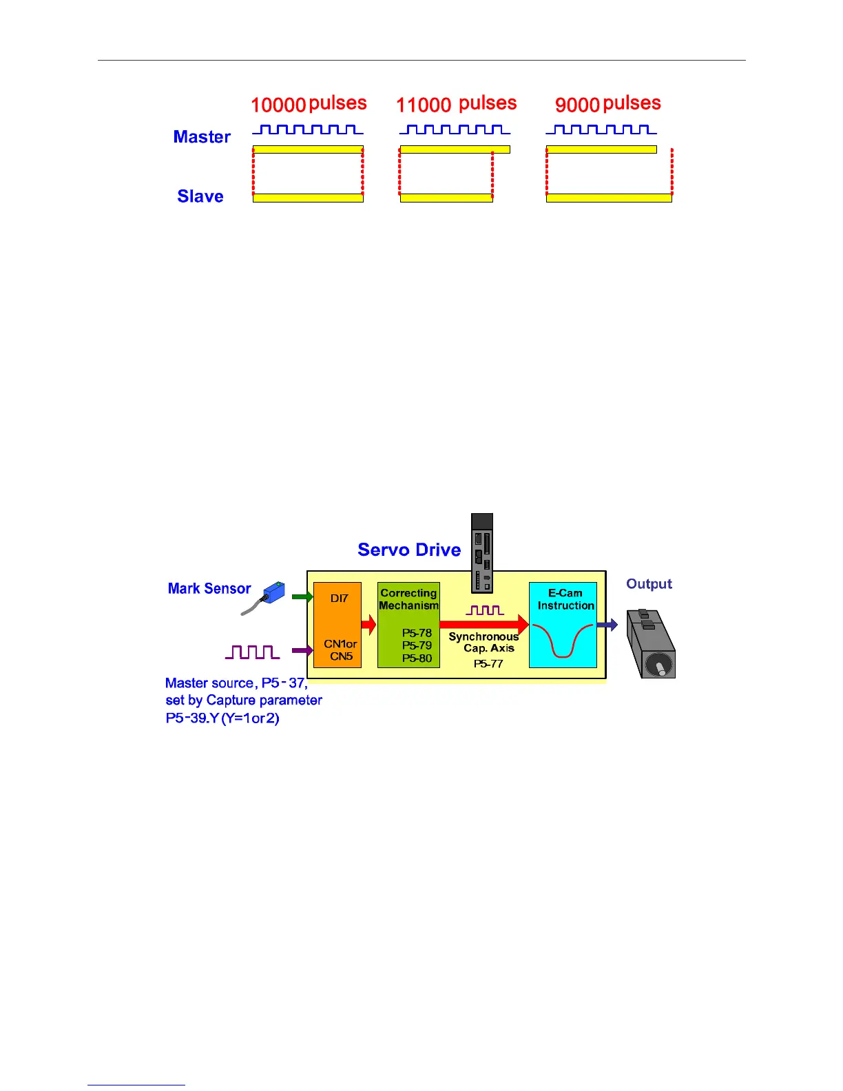
Figure 3.8.4 Relation of the Pulse from the Master Axis and the Cutting Length
In order to solve the problem of abnormal pulse sent by master axis, the pulse number between
two marks can be regarded as the basis. And the difference between the actual receiving pulses
of two marks can be the basis for adjusting the cutting length. See figure 3.8.5. After comparing
the pulse number triggered by DI7 for two times and the pulse number set by master axis, the
differences will be adjusted by correcting mechanism. The adjusted signal is the synchronous
capture axis. Use the adjusted synchronous capture axis as the master axis to drive the
camshaft. And the pulse of master axis corresponded by the camshaft will be adjusted by
synchronous capture axis. Therefore, even when the pulse number of master axis is incorrect,
the camshaft still can do the adjustment in time.
Figure 3.8.5 Synchronous Capture Axis
If the user wants to use synchronous capture axis, signal of the mark sensor must be input
by DI7 of CN1 of ASDA-A2 Servo;
The source of master axis of E-cam must set to 5. This setting is to select synchronous
capture axis as the source of master axis;
The engaging condition must set to 2 and use capturing to control the engaging time;
The pulse number between two marks must be set in P5-78. The setting of P5-78 must be
correct, or the system has no basis for comparison. Generally, P5-78 = P5-84. If P5-83 = 1,
then the distance between two marks is the distance the cam curve travels for a cycle. See
figure 3.8.6. In every cycle, the actual pulse number output by master axis between two

 Loading...


