ASDA Series Application Note Application Examples
March, 2015 3-107
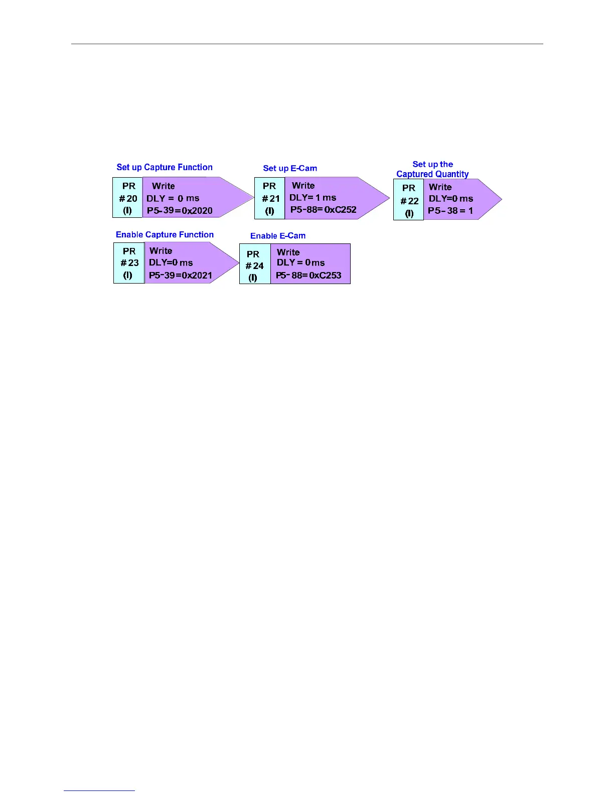
PR#22: P5-38 is to set up the captured quantity. The capture function captures one data every
cycle. Therefore, P5-38 = 1.
PR#23: Enable Capture Function, P5-39.X = 1.
PR#24: Enable E-Cam, P5-88.X1 = 1.
Figure 3.8.7 PR Setting of Synchronous Capture Axis Application on Cam
Cam Positioning
The application of cam positioning is illustrated in Figure 3.8.8. Users need to set the target
position first. The system will follow the setting and adjust it according to the difference between
the actual position and the setting one by calculating every cycle. The target position, which is
where the sensor installed, is set up by the pulse number of master axis. Take the application on
wrapping film positioning as the example. When the sensor detects the mark of the wrapping film,
the signal will be sent back to the drive. The system will check if the master axis is in the setting
position and calculate the difference of the camshaft so as to do the adjustment. For instance, if
the cam needs 36000 pulses to travel a cycle (e.g. P5-83 = 1, P5-84 = 36000), and the master
axis has 19000 pulses when setting positioning. Also, from the E-cam curve, the corresponding
position which is 9000 PUU can be known. When reading the mark, if the pulse number of
master axis is 17000, the system knows it has 2000 pulses difference from the positioning target,
the system will therefore calculate the error, 2000 pulses. With the error number calculated from
the cam curve, the correction rate which is 500 PUU can be known. This is called cam
positioning. Therefore, with the correction rate, positioning will be completed by overlap
commands.
 Loading...


