1 Basic Principles of PLC Ladder Diagram
DVP-PLC Application Manual
1-9
ORB
5 LD Y1
AND X4
6 LD T0
AND M3
ORB
7 ANB
8 OUT Y1
TMR T0 K10
Explanations on the basic structures in the ladder diagram:
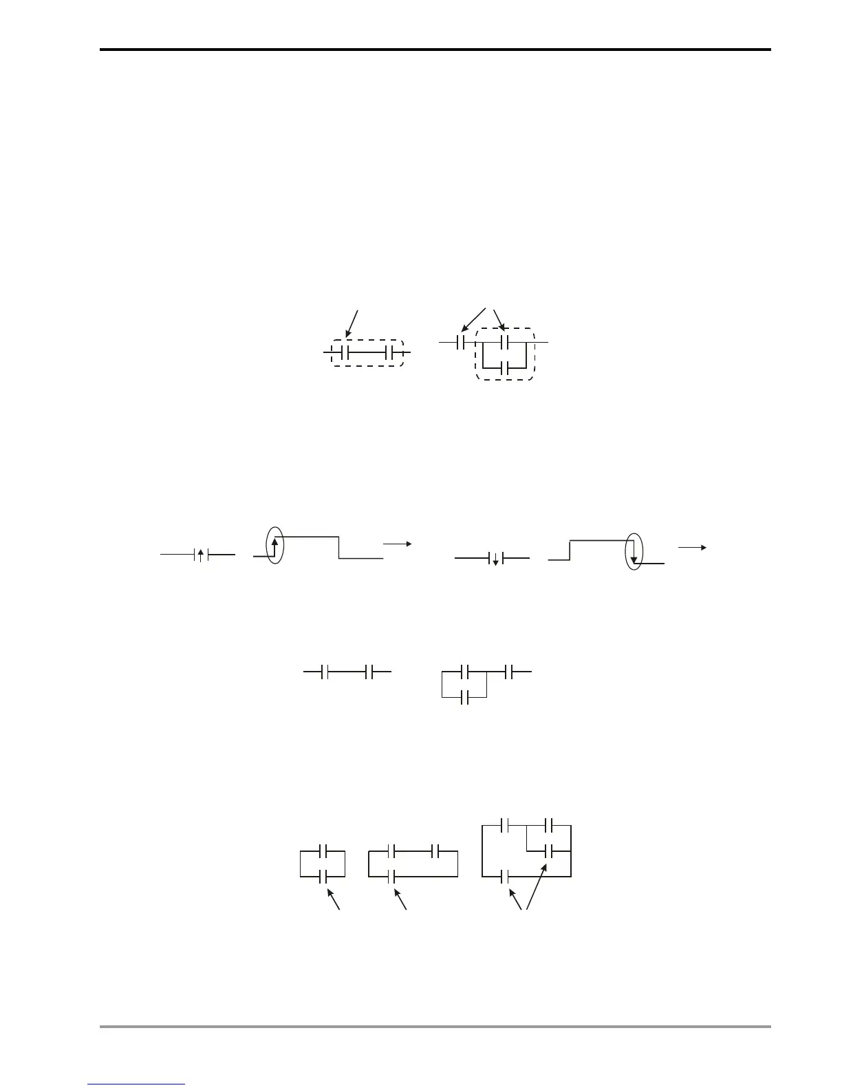
1. LD (LDI) instruction: Given in the start of a block.
AND block OR block
LD instruction LD instruction
The structure of LDP and LDF instructions are the same as that of LD instruction, and the two only differ in their
actions. LDP and LDF instructions only act at the rising edge or falling edge when the contact is On, as shown in the
figure below.
X0
OFF
ON
OFF
Time
Falling edge
X0
OFF
ON
OFF
Time
Rising edge
2. AND (ANI) instruction: A single device connects to another single device or a block in series
AND instructio
AND instruction
The structure of ANDP and ANDF instructions are the same. ANDP and ANDF instructions only act at the rising
edge or falling edge.
3. OR (ORI) instruction: A single device connects to another single device or a block
OR instruction OR instruction OR instruction
The structure of ORP and ORF instructions are the same. ORP and ORF instructions only act at the rising edge
or falling edge.