5 Categories & Use of Application Instructions
DVP-PLC Application Manual
5-14
The decimal floating point can be used in the following instructions:
D EBCD: Converting binary floating point to decimal floating point
D EBIN: Converting decimal floating point to binary floating point
Zero flag (M1020), carry flag (M1021), carry flag (M1022) and the floating point operation instructions:
Zero flag: M1020 = On if the operational result is “0”.
Borrow flag: M1021 = On if the operational result exceeds the minimum unit.
Carry flag: M1022 = On if the absolute value of the operational result exceeds the range of use.
5.4 E, F Index Register Modification
The index registers are 16-it registers. There are 2 points of E, F in ES/EX/SS, 8 points E0 ~ E3 and F0 ~ F3 in
SA/SX/SC, and 16 points E0 ~ E7 and F0 ~ F7 in EH/EH2/SV series MPU.
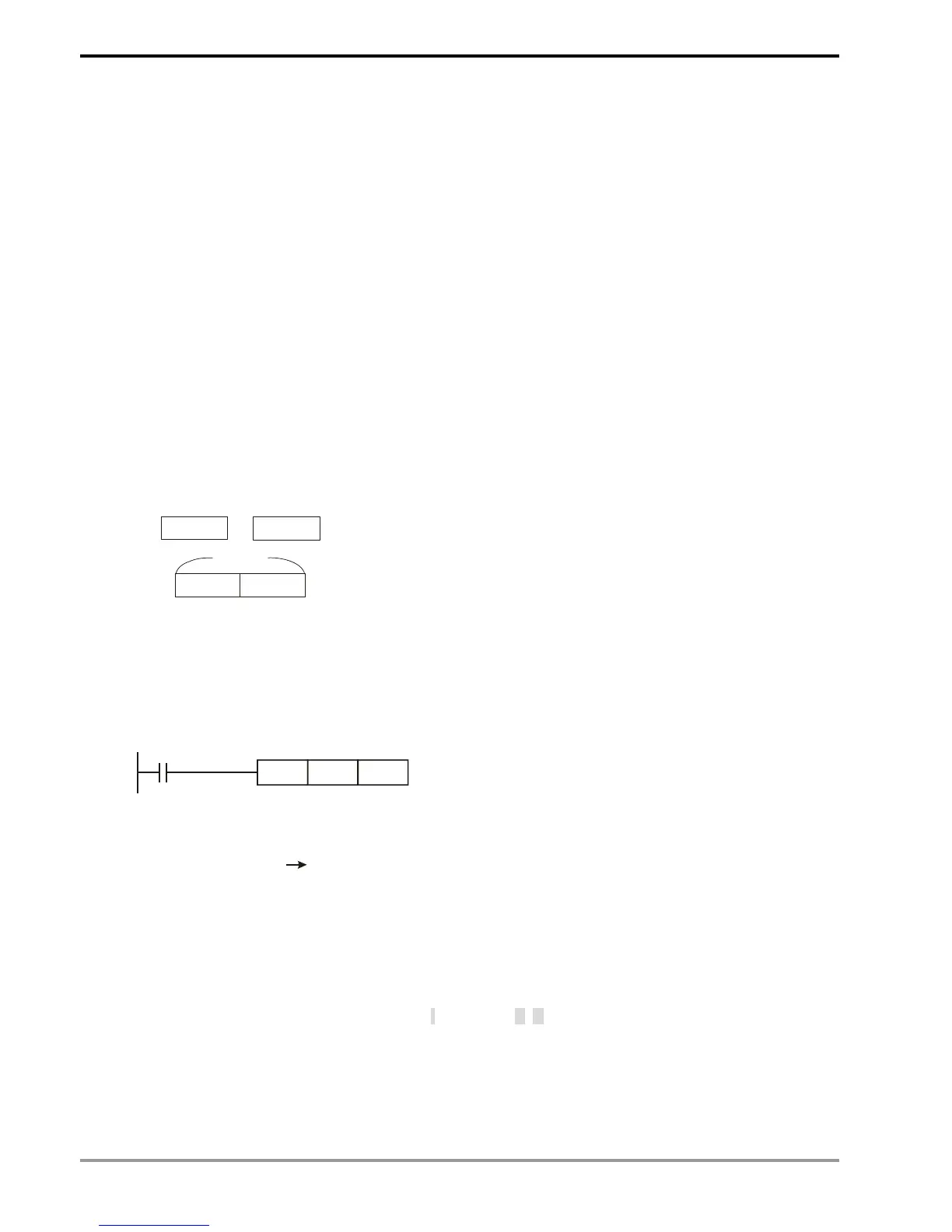
F0
E0
E0
F0
16-bit
16-bit
32-bit
High byte Low byte
E and F index registers are 16-bit data registers, can be read and
written.
If you need a 32-bit register, you have to designate E. In this case, F
will be covered up by E and cannot be used; otherwise, the contents
in E may become incorrect. (We recommend you use MOVP
instruction to reset the contents in D to 0 when the PLC is switched
on.)
Combination of E and F when you designate a 32-bit index register:
(E0, F0), (E1, F1), (E2, F2), ... (E7, F7)
MOV K20E0 D10F0
E0 = 8 F0 = 14
20 + 8 = 28 10 + 14 = 24
Transmission K28 D24
See the diagram in the left hand side. E, F index register
modification refers to the content in the operand changes with
the contents in E and F.
For example, E0 = 8 and K20E0 represents constant K28 (20
+ 8). When the condition is true, constant K28 will be
transmitted to register D24.
Devices modifiable in ES/EX/SS series MPU: P, X, Y, M, S, KnX, KnY, KnM, KnS, T, C, D.
Devices modifiable in SA/SX/SC series MPU: P, X, Y, M, S, KnX, KnY, KnM, KnS, T, C, D
Devices modifiable in EH/EH2/SV series MPU: P, I, X, Y, M, S, K, H, KnX, KnY, KnM, KnS, T, C, D
E and F can modify the devices listed above but cannot modify themselves and Kn. K4M0E0 is valid and
K0E0M0 is invalid. Grey columns in the table of operand at the beginning page of each application instruction indicate
the operands modifiable by E and F.