10 Application Instructions API 200-249
DVP-PLC Application Manual
10-7
API Mnemonic Operands Function
215~
217
D LD#
Contact Logical Operation LD#
Controllers
ES/EX/SS SA/SX/SC EH/SV
Bit Devices Word Devices Program Steps Type
OP
X Y M S K H KnX KnY KnM KnS T C D E F
S
1
* * * * * * * * ***
S
2
* * * * * * * * ***
LD#: 5 steps
DLD#: 9 steps
PULSE 16-bit 32-bit
ES EX SS SA SX SC EH SV ES EX SS SA SX SC EH SV ES EX SS SA SX SC EH SV
Operands:
S
1
: Data source device 1 S
2
: Data source device 2
Explanations:
1. See the specifications of each model for the range of operands.
2. This instruction compares the content in S
1
and S
2
. If the result is not “0”, the continuity of the instruction is
enabled. If the result is “0”, the continuity of the instruction is disabled.
3. LD#
(#: &, |, ^) instruction is used for direct connection with BUS.
API No.
16 -bit
instruction
32 -bit
instruction
Continuity
condition
No-continuity
condition
215 LD& DLD&
S
1
& S
2
≠0
S
1
& S
2
=0
216 LD| DLD|
S
1
| S
2
≠0
S
1
| S
2
=0
217 LD^ DLD^
S
1
^ S
2
≠0
S
1
^ S
2
=0
4. &: Logical “AND” operation
5. |: Logical “OR” operation
6. ^: Logical “XOR” operation
7. When 32-bit counters (C200 ~ C255) are used in this instruction for comparison, make sure to adopt 32-bit
instruction (DLD#). If 16-bit instructions (LD#) is adopted, a “program error” will occur and the ERROR
indicator on the MPU panel will flash.
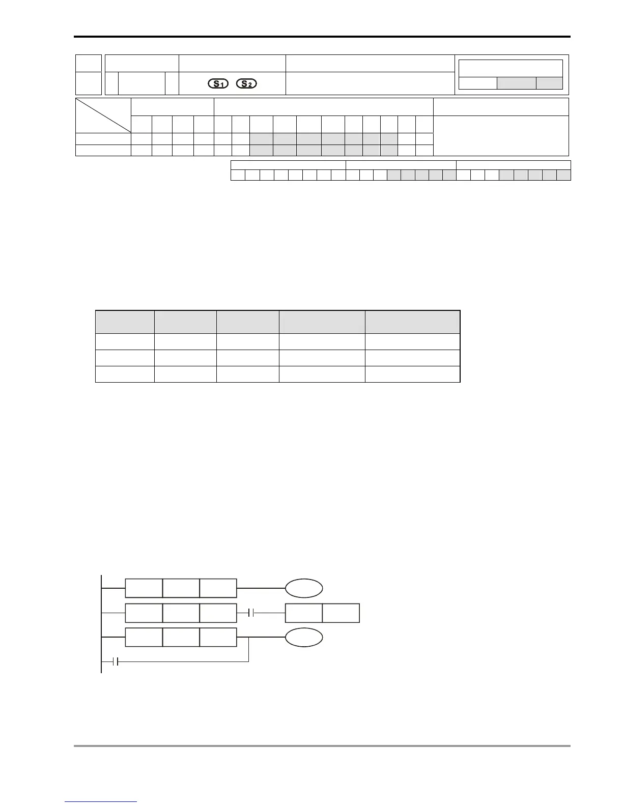
Program Example:
1. When the result of logical AND operation of C0 and C10 ≠ 0, Y10 = On.
2. When the result of logical OR operation of D200 and D300 ≠ 0 and X1 = On, Y11 = On will be retained.
3. When the result of logical XOR operation of C201 and C200 ≠ 0 or M3 = On, M50 = On.
M3
DLD
C201 C200
M50
LD
C0 C10
LD
D200 D300
SET
X1
&
^
I
Y011
Y10