8 Application Instructions API 100-149
DVP-PLC Application Manual
8-14
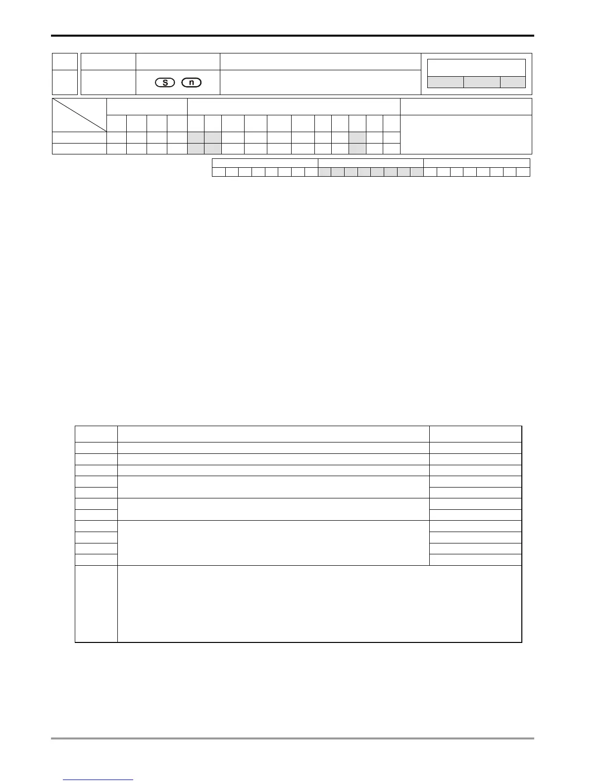
API Mnemonic Operands Function
105
RDST
Read VFD-A Status
Controllers
ES/EX/SS SA/SX/SC EH/SV
Bit Devices Word Devices Program Steps Type
OP
X Y M S K H KnX KnY KnM KnS T C D E F
S
* * *
n * * *
RDST: 5 steps
PULSE 16-bit 32-bit
ES EX SS SA SX SC EH SV ES EX SS SA SX SC EH SV ES EX SS SA SX SC EH SV
Operands:
S: Address of communicatino device n: Target to be instructed
Explanations:
1. Range of S: K0 ~ K31
2. Range of n: K0 ~ K3
3. See the specifications of each model for their range of use.
4. ES series MPU does not support E, F index register modification.
5. Flags: See API 80 RS for explanations on M1120 ~ M1131, M1140 ~ M1143
6. n: Instructed target (to be read) in AC motor drive
n=0, frequency
n=1, output frequency
n=2, output current
n=3, running instruction
7. Data sent back (feedback) from AC motor drive (11 bytes, see VFD-A user manual) are stored in the low bytes
of D1070 ~ D1080.
”Q, S, B, Uu, Nn, ABCD”
Feedbac
Explanation Data storage
Q Start word: ’Q’ (51H). D1070 low
S Checksum code: 03H. D0171 low
B Instruction authorization. correct: 06H, incorrect: 07H. D1072 low
U D1073 low
U
Communication address (address: 00~31). ”Uu” = (“00” ~ ”31”) indicated
in ASCII format.
D1074 low
N D1075 low
N
Instructed target (00 ~ 03).”Nn” = (“00 ~ 03”) indicated in ASCII format.
D1076 low
A D1077 low
B D1078 low
C D1079 low
D
Instructed data. The content of ”ABCD” differs upon the instructed targets
(00 ~ 03). 00 ~ 03 indicate frequency, current and running mode
respectively. Please refer to the explanations below for details.
D1080 low
Nn = “00” Frequency instruction = ABC.D (Hz)
Nn = “01” Output instruction = ABC.D (Hz)
Nn = “02” Output current = ABC.D (A)
PLC will automatically convert the ASCII characters of ”ABCD” into numerals and store the
numeral in D1050. For example, assume ”ABCD” = “0600”, PLC will convert ABCD into K0600
(0258 H) and store it in the special register D1050.