7 Application Instructions API 50-99
DVP-PLC APPLICATION MANUAL
7-76
API Mnemonic Operands Function
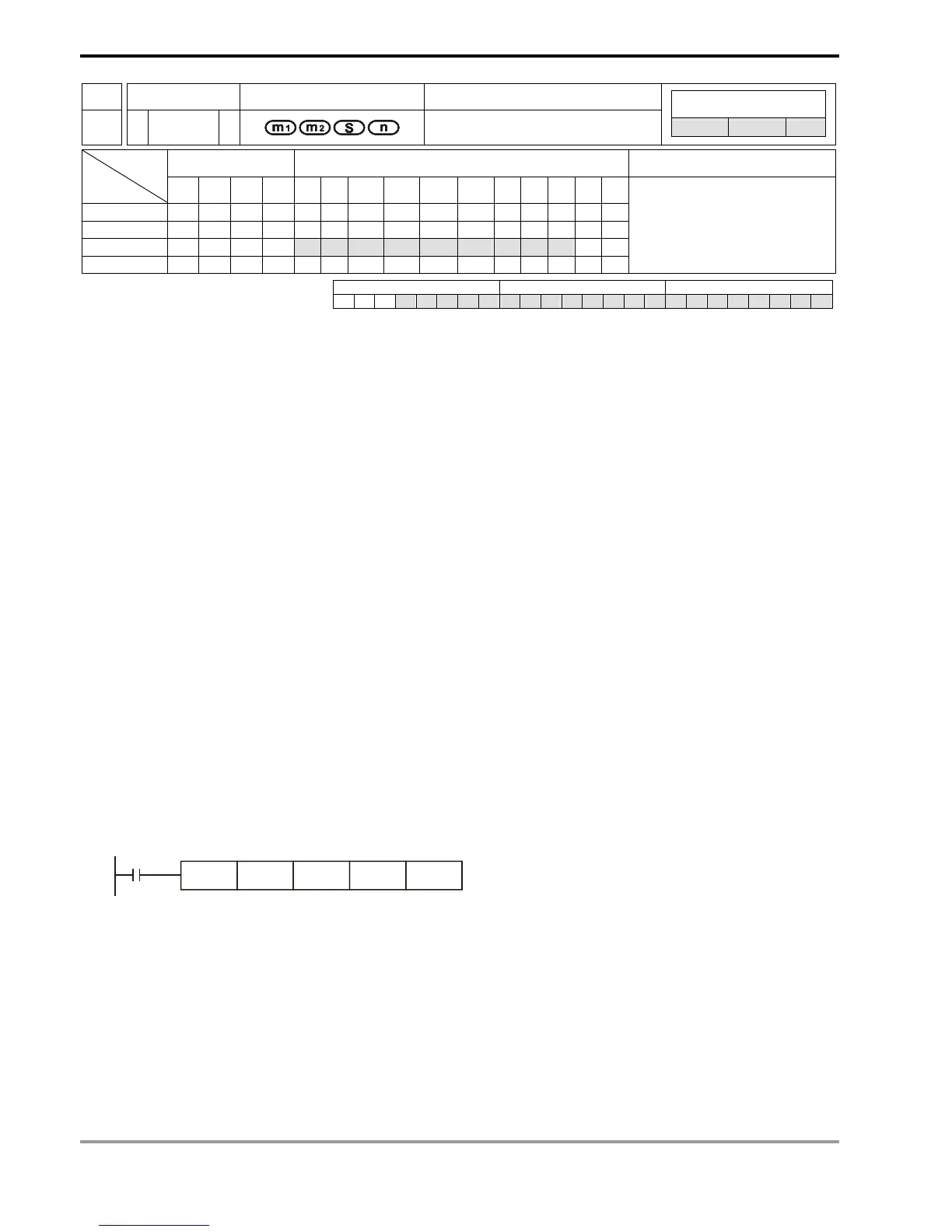
79
D TO P
Write CR Data into Special
Modules
Controllers
ES/EX/SS SA/SX/SC EH/SV
Bit Devices Word Devices Program Steps Type
OP
X Y M S K H KnX KnY KnM KnS T C D E F
m
1
* * *
m
2
* * *
S * * * * * * * * * * *
n * * *
TO, TOP: 9 steps
DTO, DTOP: 17 steps
PULSE 16-bit 32-bit
ES EX SS SA SX SC EH SV ES EX SS SA SX SC EH SV ES EX SS SA SX SC EH SV
Operands:
m
1
: No. of special module m
2
: CR# in special module to be written S: Data to be written in CR n: Number
of data to be written at a time
Explanations:
1. Range of m
1
(16-bit and 32-bit): for ES/SA: 0 ~ 7, for EH/EH2: 0 ~ 255, for SV: 0 ~ 107.
2. Range of m
2
(16-bit and 32-bit): for ES/SA: 0 ~ 48, for EH: 0 ~ 254, for EH2/SV: 0 ~ 499.
3. Range of n:
a) 16-bit: for ES/SA: 1 ~ (49 – m
2
), for EH: 1 ~ (255 – m
2
), for EH2/SV: 1 ~ (500 – m
2
).
b) 32-bit: for ES/SA: 1 ~ (49 – m
2
)/2, for EH: 1 ~ (255 – m
2
)/2, for EH2/SV: 1 ~ (500 – m
2
)/2.
4. ES series MPU does not support E, F index register modification.
5. m
1
, m
2
and n of EH series MPU do not support word device D.
6. Flag: M1083 (On when allowing interruptions during FROM/TO instruction). See remarks for more details.
7. This instruction is for writing the data into the CR in special modules.
8. The 16-bit instruction can designate S = K1 ~ K4; the 32-bit instruction can designate S = K1 ~ K8.
Program Example:
1. Use 32-bit instruction DTO to write the content in D11 and D10 into CR#13 and CR#12 of special module No.0.
Only 1 group of data is written in at a time (n = 1).
2. When X0 = On, the instruction will be executed. When X0 = Off, the instruction will not be executed and the data
written will not be changed.
X0
DTO K0 K12 D10 K1
3. Operand rules
a) m
1
: The No. of special modules connected to PLC MPU. No. 0 is the module closest to te MPU. Maximum 8
modules are allowed to connected to a PLC MPU and they will not occupy any I/O points.
b) m
2
: CR#. CR (control register) is the n 16-bit memories built in the special module, numbered in decimal as
#0 ~ #n. All operation status and settings of the special module are contained in the CR.
c) FROM/TO instruction is for reading/writing 1 CR at a time. DFROM/DTO instruction is for reading/writing 2
CRs at a time.