Designated CR number
Hi gher 16 -bit
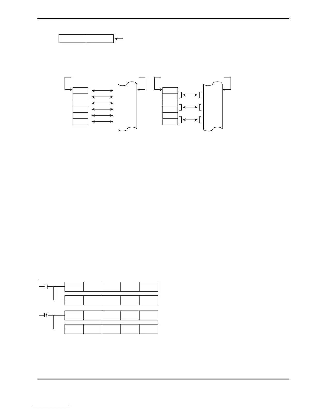
d) Number of groups “n” to be transmitted: n = 2 in 16-bit instructions and n = 1 in 32-bit instructions mean
the same.
D0
D1
D2
D3
D4
D5
CR #5
CR #6
CR #7
CR #8
CR #9
CR #10
D0
D1
D2
D3
D4
D5
CR #5
CR #6
CR #7
CR #8
CR #9
CR #10
Designated device
Designated CR
Designated device
Designated CR
16-bit instruction when n=6
32-bit instruction when n=3
4. ES/EX/SS series MPU does not have M1083. During the execution of FROM/TO instruction, all external or
internal interruption subroutines will be forbidden. The interruptions are allowed only after FROM/TO instruction
finishes its execution. FROM/TO instruction can also be used in an interruption subroutine.
5. M1083 for switching instruction modes in SA/SX/SC/EH/EH2/SV series MPU:
a) When M1083 = Off, during the execution of FROM/TO instruction, all external or internal interruption
subroutines will be forbidden. The interruptions are allowed only after FROM/TO instruction finishes its
execution. FROM/TO instruction can also be used in an interruption subroutine.
b) When M1083 = On and an interruption signal occurs during the execution of FROM/TO instruction, the
interruption will be processed first (with a 100us delay) and the execution of FROM/TO will be stopped. After
the interruption subroutine finishes its execution, the program will jump to the next instructio of FROM/TO.
FROM/TO cannot be used in an interruption subroutine.
FROM/TO Application Example 1:
Adjust the A/D conversion curve of DVP-04AD. Set the OFFSET value of CH1 as 0V (= K0
LSB
) and GAIN value as
2.5V (= K2,000
LSB
).
M1002
TO K0 K1 H0 K1
TO K0 K33 H0 K1
X0
TO
K0 K18 K0 K1
TO
K0 K24 K2000 K1
1. Write H0 to CR#1 of anlog input module No. 0 and set CH1 as mode 0 (voltage input: -10V ~ +10V).
2. Write H0 to CR#33 and allow OFFSET/GAIN tuning in CH1 ~ CH4.
3. When X0 goes from Off to On, write the OFFSET value K0
LSB
into CR#18 and the GAIN value K2,000
LSB
into