5 Categories & Use of Application Instructions
DVP-PLC Application Manual
5-11
API 103 REV (ES/SA/EH), API 104 STOP (ES/SA/EH), API 105 RDST (ES/SA/EH), API 106 RSTEF
(ES/SA/EH), API 150 MODRW (ES/SA/EH), API 151 PWD (EH).
2. Instructions which can be executed only twice: API 57 PLSY (EH), API 58 PWM (SA/EH), API 59 PLSR (SA/EH),
API 72 DSW (EH).
3. Instructions which can be executed only 4 times: API 57 PLSY (EH2/SV), API 58 PWM (EH2/SV), API 169
HOUR (EH).
4. Instructions which can be executed only 8 times: API 64 TTMR (EH).
5. In SA series MPU, there is on limitation on the times of using the high-speed output instructions PLSY, PWM and
PLSR, bit only one high-speed output instruction will be enabled in every scan.
6. In EH series MPU, there is no limitation on the times of using hardware high-speed counter instructions DHSCS,
DHSCR and DHSZ, but when the three instructions are enabled at the same time, DHSCS will occupy 1 memory
unit, DHSCR 1 memory unit, and DHSZ 2 memory units. The total memeory units occupied by the three
instructions cannot be more than 8 units. If there are more than 8 memory units occupied, the PLC system will
execute the instruction that is first scanned and enabled and ignore the rest.
5.3 Handling of Numeric Values
Devices only with On/Off status are called bit devices, e.g. X, Y, M and S. Devices used exclusively for storing
numeric values are called word devices, e.g. T, C, D, E and F. Bit device plus a specific bit device (place a digit
before the bit device in Kn) can be used in the operand of an application instruction in the form of numeric value.
n = K1 ~ K4 for a 16-bit value; n = K1 ~ K8 for a 32-bit value. For example, K2M0 refers to a 8-bit value composed of
M0 ~ M7.
M15 M14 M13 M12 M11 M10 M9 M8 M7 M6 M5 M4 M3 M2 M0M1
00000000
00001 1 1 1
11111111
D1
D1
1111000000000000
b15 b14 b13 b12 b11 b10 b9 b8 b7 b6 b5 b4 b3 b2 b0b1
0000000
0
Valid data
Reset to 0
Transmit to
Equals
Low byte
Low byte
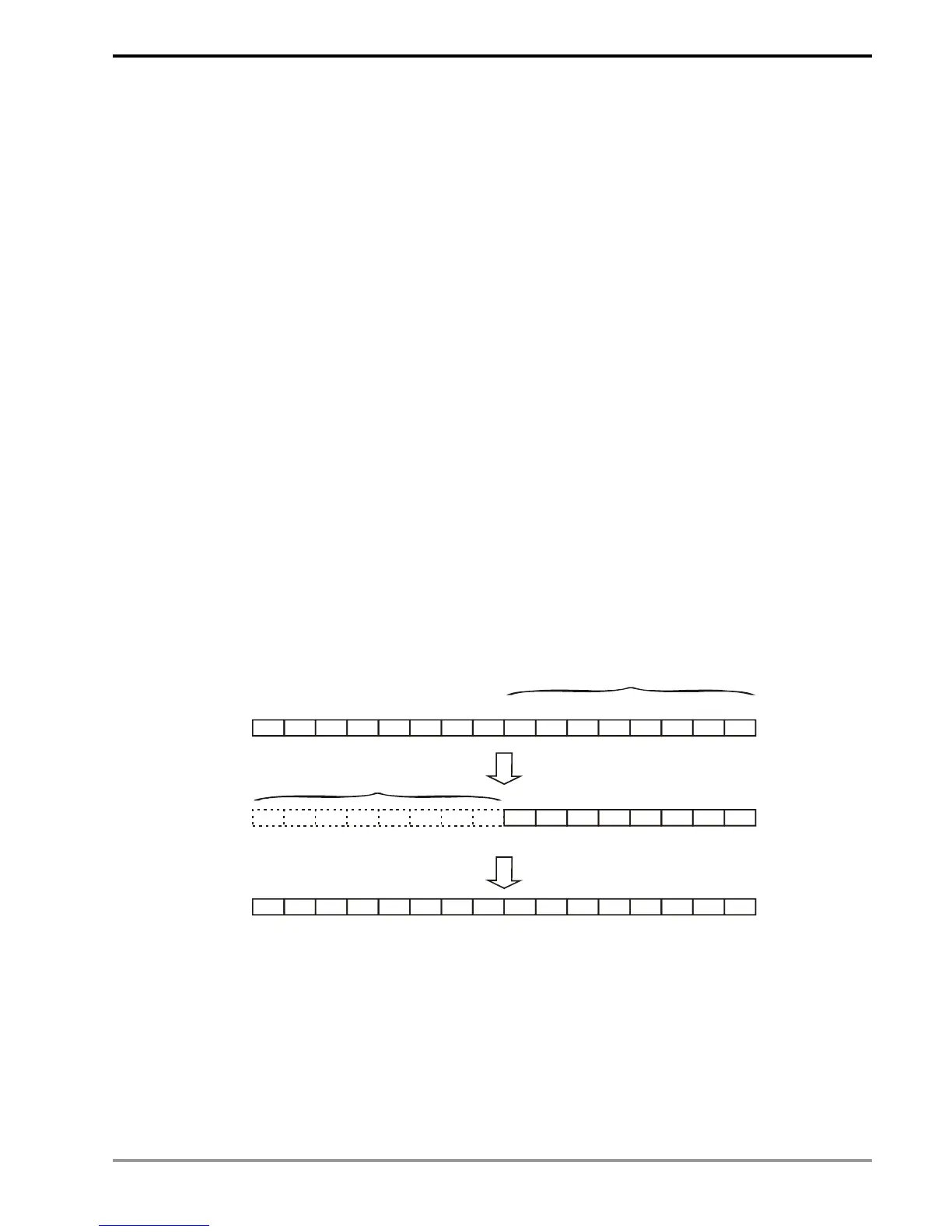
K1M0, K2M0, and K3M0 are transmitted to 16-bit registers and the vacant high bits will be filled in “0”. The same
rule applied to when K1M0, K2M0, K3M0, K4M0, K5M0, K6M0, and K7M0 are transmitted to 32-bit registers and
the vacant high bits will be filled in “0”.
In the 16-bit (or 32-bit) operation, if the contents of the operand are designated as bit devices K1 ~ K3 (or K4 ~ K7),
the vacant high bits will be regarded as “0”. Therefore, the operation is a positive-value one.