7 Application Instructions API 50-99
DVP-PLC APPLICATION MANUAL
7-24
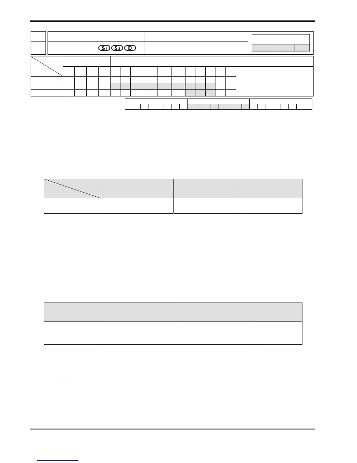
API Mnemonic Operands Function
56
SPD
Speed Detection
Controllers
ES/EX/SS SA/SX/SC EH/SV
Bit Devices Word Devices Program Steps Type
OP
X Y M S K H KnX KnY KnM KnS T C D E F
S
1
*
S
2
* * * * * * * * * * *
D * * *
SPD: 7 steps
PULSE 16-bit 32-bit
ES EX SS SA SX SC EH SV ES EX SS SA SX SC EH SV ES EX SS SA SX SC EH SV
Operands:
S
1
: External pulse input terminal S
2
: Pulse receiving time (ms) D: Detected result
Explanations:
1. See the specifications of each model for their range of use.
2. Flag: M1100 (SPD instruction performs sampling for one time)
3. External pulse input terminals designated in S
1
for all series MPU:
MPU
Input
ES/EX/SS (V5.7and above) SA/SX/SC EH/EH2/SV
Available input points
X1, X2 X0, X1, X2 X0 ~ X3
4. For SA/SX (V1.4 and above) series MPU and SC (V1.2 and above) series MPU, the new X0 and X1 can be
used together with A-B phase input points. When “A ahead of B” detection result is a positive value and “B
ahead of A” detection result is a negative value, the multiplied frequency of the counter can be set by D1022.
5. The received number of pulses of the input terminal designated in S
1
is calculated within the time (in ms)
designated in S
2
. The result is stored in the register designated in D.
6. D will occupy 5 consecutive devices. D + 1 and D are the detected value obtained from the previous pulses; D
+3 and D + 2 are the current accumulated number of values; D + 4 is the counting time remaining (max.
32,767ms).
7. Pulse frequency detection for all series:
MPU ES/EX/SS (V5.7 and above) SA/SX/SC EH/EH2/SV
Max. frequency
X1 (20KHz), X2 (10KHz)
X0/X1 A-B phase input (4KHz)
X1 (30KHz), X2 (10KHz)
X0/X1 (100KHz)
X2/X3 (10KHz)
8. This instruction is mainly used for obtaining a proportional value of rotation speed. The result D and rotation
speed will be in proportion. The following equation is for obtaining the rotation speed of motor.
N: Rotation speed
n: The number of pulses produced per rotation
N=
()
()
rpm10×
nt
0D60
3
t: Detecting time designated in S
2
(ms)
9. The X input point designated by this instruction cannot be used again as the pulse input terminal of the high
speed counter or as an external interruption signal.
10. When M1036 in SC (V1.4 and above) series MPU is enabled, SPD instruction can detect the speeds at X0 ~ X5