7 Application Instructions API 50-99
DVP-PLC APPLICATION MANUAL
7-78
CR#24.
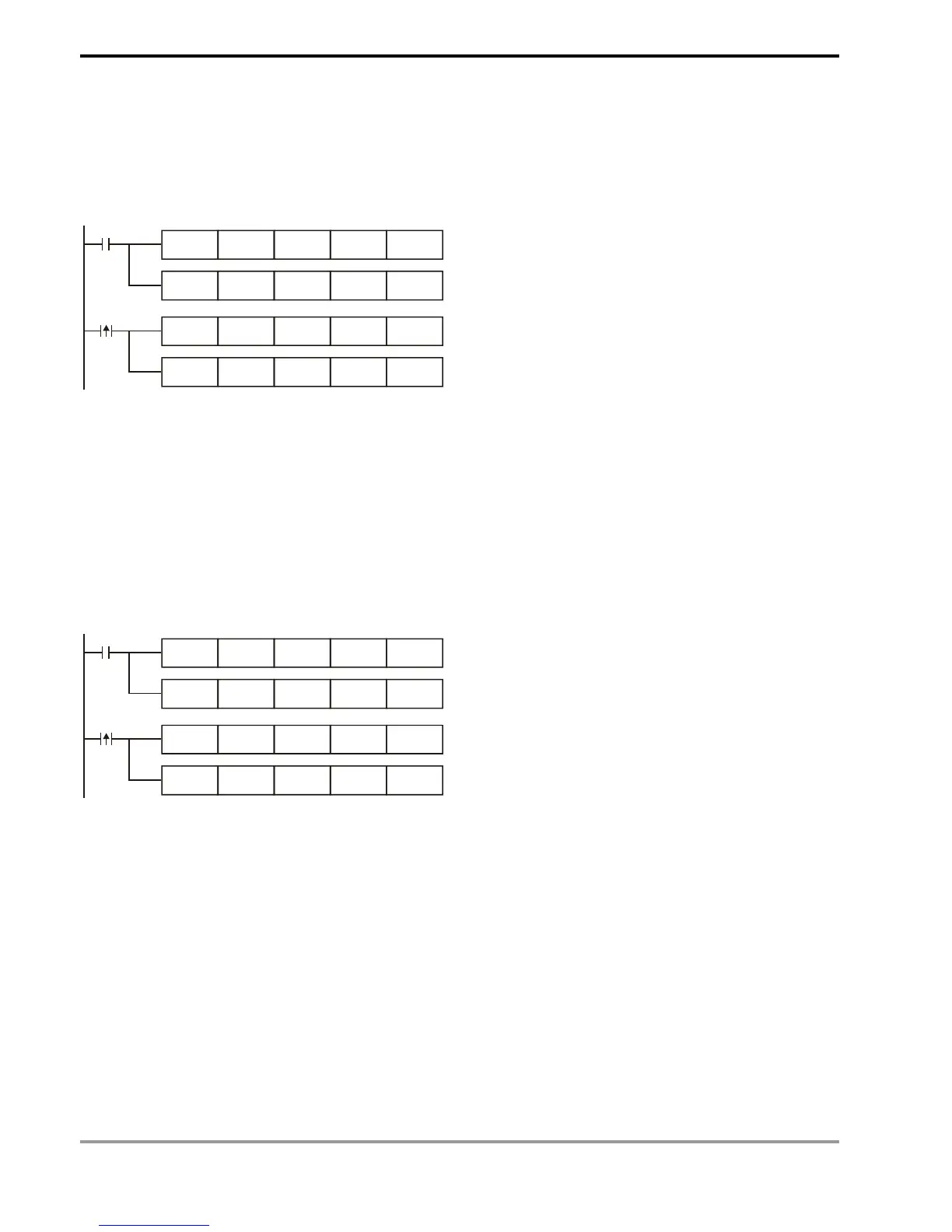
FROM/TO Application Example 2:
Adjust the A/D conversion curve of DVP-04AD. Set the OFFSET value of CH2 as 2mA (= K400
LSB
) and GAIN value
as 18mA (= K3,600
LSB
).
M1002
TO K0 K1 H18 K1
TO K0 K33 H0 K1
X0
TO
K0 K19 K400 K1
TO
K0 K25 K3600 K1
1. Write H18 to CR#1 of anlog input module No. 0 and set CH2 as mode 3 (current input: -20mA ~ +20mA).
2. Write H0 to CR#33 and allow OFFSET/GAIN tuning in CH1 ~ CH4.
3. When X0 goes from Off to On, write the OFFSET value K400
LSB
into CR#19 and the GAIN value K3,600
LSB
into
CR#25.
FROM/TO Application Example 3:
Adjust the D/A conversion curve of DVP-02DA. Set the OFFSET value of CH2 as 0mA (= K0
LSB
) and GAIN value as
10mA (= K1,000
LSB
).
M1002
TO K1 K1 H18 K1
TO K1 K33 H0 K1
X0
TO
K1 K22 K0 K1
TO
K1 K28 K1000 K1
1. Write H18 to CR#1 of anlog output module No. 1 and set CH2 as mode 3 (current output: 0mA ~ +20mA).
2. Write H0 to CR#33 and allow OFFSET/GAIN tuning in CH1 and CH2.
3. When X0 goes from Off to On, write the OFFSET value K0
LSB
into CR#22 and the GAIN value K1,000
LSB
into
CR#28.
FROM/TO Application Example 4:
Adjust the D/A conversion curve of DVP-02DA. Set the OFFSET value of CH2 as 2mA (= K400
LSB
) and GAIN value
as 18mA (= K3,600
LSB
).
1. Write H10 to CR#1 of anlog output module No. 1 and set CH2 as mode 2 (current output: +4mA ~ +20mA).
2. Write H0 to CR#33 and allow OFFSET/GAIN tuning in CH1 and CH2.
3. When X0 goes from Off to On, write the OFFSET value K400
LSB
into CR#23 and the GAIN value K3,600
LSB
into
CR#29.