8 Application Instructions API 100-149
DVP-PLC Application Manual
8-15
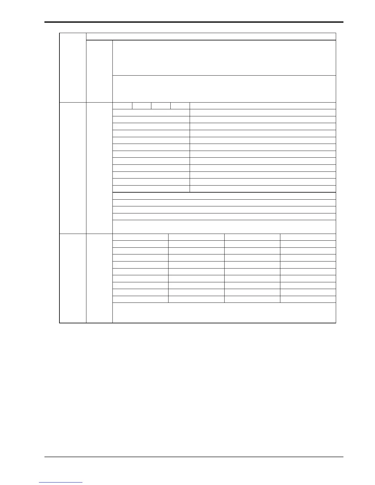
Nn = “03” Running instruction
‘A’ = ‘0’ Stop, ‘5’ JOG (forward)
‘1’ Forward running ‘6’ JOG (reverse)
‘2’ Stop, ‘7’ JOG (reverse)
‘3’ Reverse running ‘8’ Abnormal
‘4’ JOG (forward),
ES series PLCs will convert the ASCII characters of ”A” into a numeral and store the
numeral in D1051. For example, assume ”A” = “3”, PLC will convert A into K3 and
store it in the special register D1051. SA/EH series PLCs will store the numeral in low
bytes of D1051.
‘B’ = b7 b6 b5 b4 Source of running instruction
0 0 0 0 Digital keypad
0 0 0 1 1
st
Step Speed
0 0 1 0 2
nd
Step Speed
0 0 1 1 3
rd
Step Speed
0 1 0 0 4
th
Step Speed
0 1 0 1 5
th
Step Speed
0 1 1 0 6
th
Step Speed
0 1 1 1 7
th
Step Speed
1 0 0 0 JOG frequency
1 0 0 1 Analog signal frequency instruction
1 0 1 0 RS-485 communication interface
1 0 1 1 Up/Down control
b3 = 0 No DC braking stop 1 DC braking stop
b2 = 0 No DC braking startup 1 DC braking startup
b1 = 0 Forward running 1 Reverse running
b0 = 0 Stop 1 Running
ES series PLCs will store ”B” in special auxiliary relay M1168 (b0) ~ M1175 (b7).
SA/EH series PLCs will store “B” (in hex) in the high bytes of special register D1051.
“CD” = “00” No abnormal record “10” OcA
“01” oc “11” Ocd
“02” ov “12” Ocn
“03” oH “13” GFF
“04” oL “14” Lv
“05” oL1 “15” Lv1
“06” EF “16” cF2
“07” cF1 “17” bb
“08” cF3 “18” oL2
“09” HPF “19”
ES/SA/EH series PLCs will convert the ASCII characters of ”CD” into a numerals and
store the numeral in D1052. For example, assume ”CD” = “16”, PLC will convert CD
into K16 and store it in the special register D1052.
Remarks:
1. The activation criteria placed before the three instructions, API 100 MODRD, API 105 RDST and API 150
MODRW (Function Code 03), cannot use rising-edge contacts (LDP, ANDP ORP) and falling-edge contacts
(LDF, ANDF, ORF); otherwise, the data stores in the receiving registers will be incorrect.
2. For the registers for flag settings, see explanations in API 80 RS.
3. There is no limitation on the times of using this instruction in the program, but only one instruction is allowed to
be executed at a time.
 Loading...