EasyManuals Logo

Delta DVP-PLC User Manual

Delta DVP-PLC
586 pages
To Next Page IconTo Next Page
To Previous Page IconTo Previous Page
Page #15 background imageLoading...
Page #15 background image
1 Basic Principles of PLC Ladder Diagram
DVP-PLC Application Manual
1-11
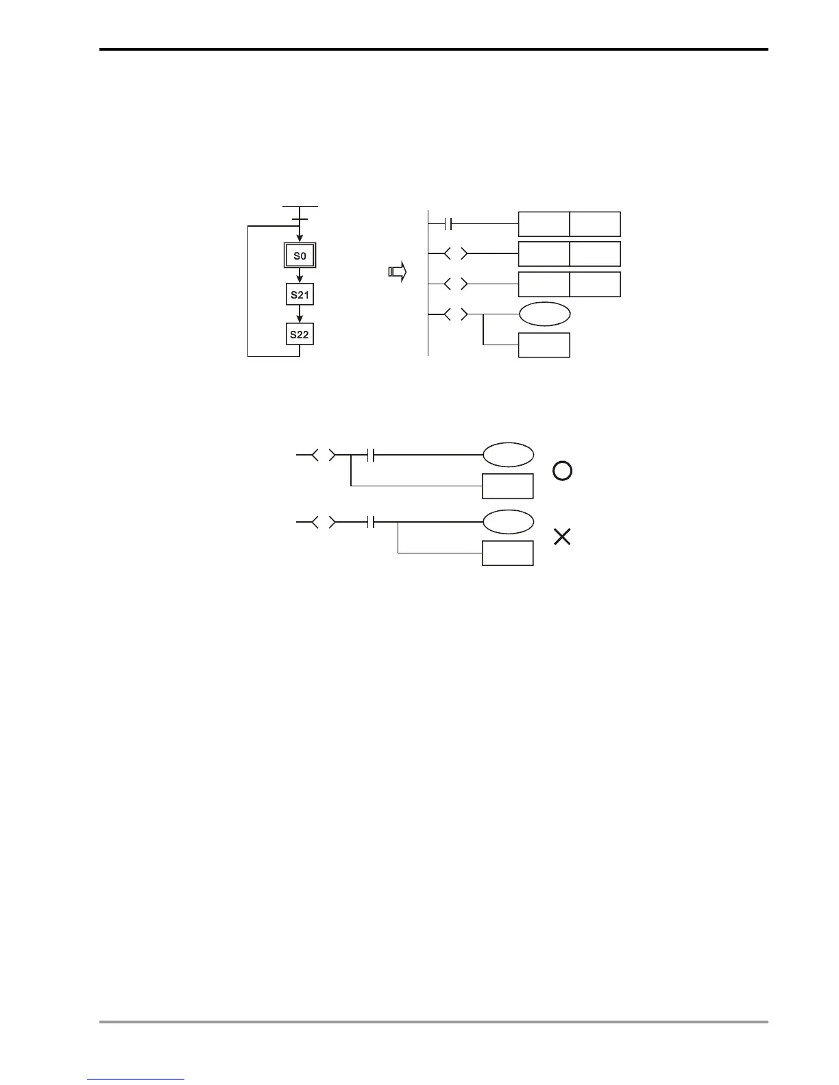
7. STL instruction: Used for designing the syntax of the sequential function chart (SFC).
STL instruction allows the program designer a clearer and readable picture of the sequence of the program as
when they draw a sequence chart. From the figure below, we can see clearly the sequence to be planned. When the
step S moves to the next step, the original S will be “Off". Such a sequence can then be converted into a PLC ladder
diagram and called “step ladder diagram”.
M1002
S0
SET
S0
S0
SET
S21
SET
S22
S
S21
S
RET
S22
S
M1002
8. RET instruction: Placed after the completed step ladder diagram.
RET also has be placed after STL instruction. See the example below.
RET
S20
S
RET
S20
S
X1
X1
See step ladder instructions [STL], [RET] in Ch. 4 for the structure of the ladder diagram.

Table of Contents

Questions and Answers:

Question and Answer IconNeed help?

Do you have a question about the Delta DVP-PLC and is the answer not in the manual?

Delta DVP-PLC Specifications

General IconGeneral
ManufacturerDelta Electronics
ModelDVP-PLC
CategoryController
Humidity5% to 95% RH, non-condensing
Programming LanguageLadder Diagram (LD), Instruction List (IL), Sequential Function Chart (SFC)
CPU TypeVarious, depending on the specific model within the DVP series (e.g., ES2, EX2, SX2, SA2, EH3, etc.)
Operating TemperatureTypically 0°C to 55°C (32°F to 131°F)
Storage TemperatureTypically -25°C to 70°C (-13°F to 158°F)

Related product manuals