3 Basic Instructions
DVP-PLC Application Manual
3-11
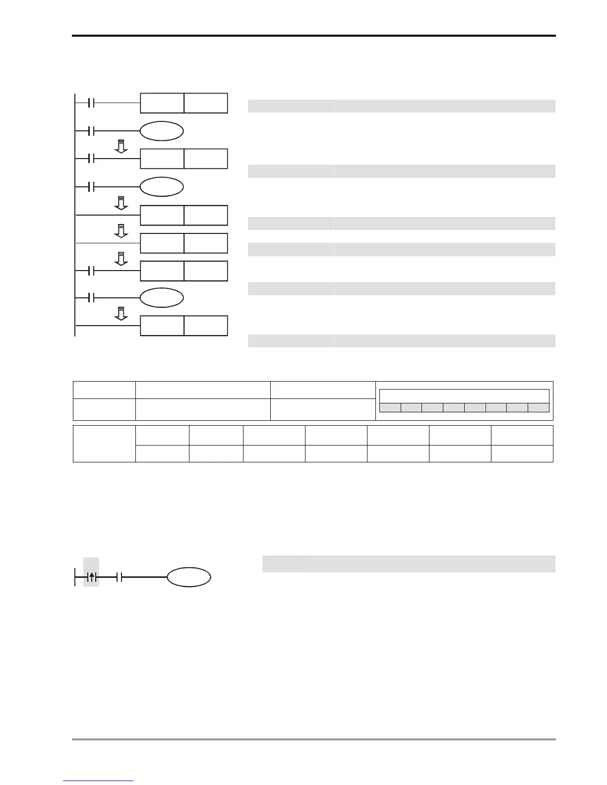
Program Example:
Ladder diagram: Instruction code: Operation:
LD X0 Loading in A contact of X0
MC N0 Enabling N0 common series connection contact
LD X1 Loading in A contact of X1
OUT Y0 Driving Y0 coil
:
LD X2 Loading in A contact of X2
MC N1 Enabling N1 common series connection contact
LD X3 Loading in A contact of X3
OUT Y1 Driving Y1 coil
:
MCR N1 Disabling N1 common series connection contact
:
MCR N0 Disabling N0 common series connection contact
:
LD X10 Loading in A contact of X10
MC N0 Enabling N0 common series connection contact
LD X11 Loading in A contact of X11
OUT Y10 Driving Y10 coil
:
MCR N0 Disabling N0 common series connection contact
X0
Y0
MC N0
X1
X2
Y1
MC N1
X3
MCR N1
MCR N0
X10
MC N0
Y10
X11
MCR N0
Mnemonic Function Program steps
LDP
Rising-edge detection
operation
1
Controllers
ES EX SS SA SX SC EH SV
X0 ~ X377 Y0 ~ Y377 M0 ~ M4095 S0 ~ S1023 T0 ~ T255 C0 ~ C255 D0 ~ D9999
Operand
9 9 9 9
9
9
-
Explanations:
The method of using LDP is the same as using LD, but the actions of the two instructions differ. LDP saves the current
content and store the detected status of rising-edge to the accumulative register.
Program Example:
Ladder diagram: Instruction code: Operation:
LDP X0
Starting X0 rising-edge detection
AND X1 Series connecting A contact of X1
X0 X1
Y1
OUT Y1 Driving Y1 coil
Remarks:
1. See the specification of each model for the range of operands.
2. If the status of a designated rising-edge is On before the PLC is powered, the contact of the rising-edge will be
TRUE after PLC is powered.