1 Basic Principles of PLC Ladder Diagram
DVP-PLC Application Manual
1-16
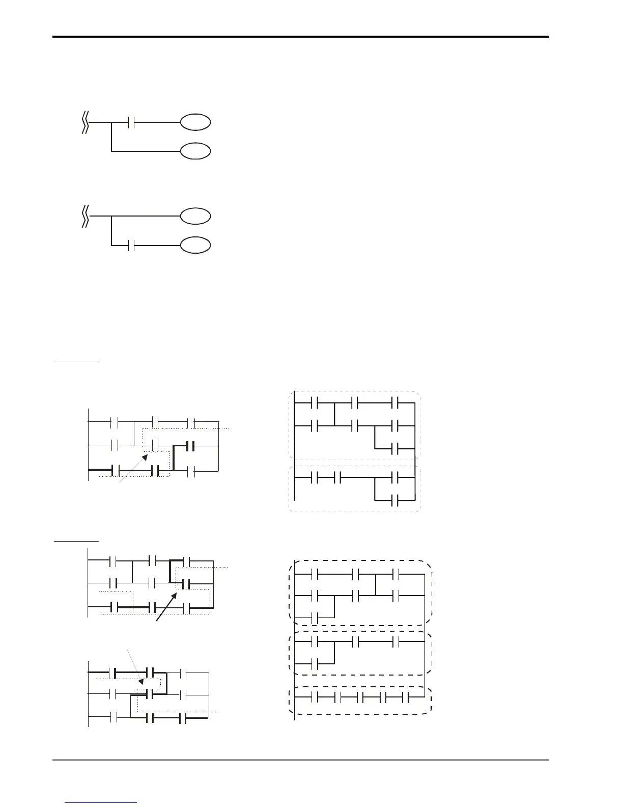
MPS and MPP instruction can be omitted when the multiple outputs in the same horizontal line do not need to
operate with other input devices.
Ladder diagram complied into instruction
MPS
AND X0
OUT Y1
MPP
X0
Y1
Y0
Ø
OUT Y0
Ladder diagram complied into instruction
OUT Y0
AND X0
Y0
Y1
X0
OUT Y1
Correct the circuit of reverse flow
In the following two examples, the diagram in the left hand side is the ladder diagram we desire. However, the illegal
“reverse flow” in it is incorrect according to our definition on the ladder diagram. We modify the diagram into the
diagram in the right hand side.
Example 1
X0
X3
X6
X1
X4
X7
X2
X5
X10
LOOP 1
rever se flo