7 Application Instructions API 50-99
DVP-PLC APPLICATION MANUAL
7-4
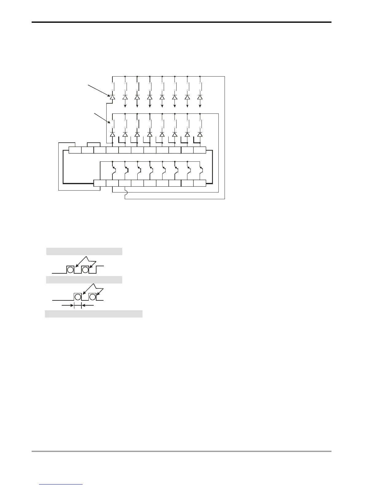
2. The figure below illustrates the external wiring of the 2-array matrix input loop constructed by X40 ~ X47 and
Y40 ~ Y41. The 16 switches correponds to the internal relays M10 ~ M17, M20 ~ M27. Should be used with
MTR instruction.
S/S X40 X41 X42 X43 X44 X45 X47X46
C
Y40 Y41 Y42 Y43 Y44 Y45 Y47Y46
M10
X41
M20
M11 M12 M13 M14 M15 M16 M17
X42 X43 X44 X45 X46 X47
M21 M22 M23 M24 M25 M26 M27
+24V
24G
M10: the internal relay
corresponding to
the external switch
Must connect to the diode
of 0.1A/50V, 1N4148, in series
3. See the figure above. The 8 points starting from X40 start to perform a matrix scan from Y40 ~ Y41 (n = 2). D
2
designates that the start device No. of the read results is M10, indicating that the first array is read to M10 ~
M17 and the second array is read to M20 ~ M27.
2 4
Y41
Y40
25ms
1 3
Read input signals in the 1st array
Read input signals in the 2nd array
Processing time of each array: approx. 25ms