7 Application Instructions API 50-99
DVP-PLC APPLICATION MANUAL
7-20
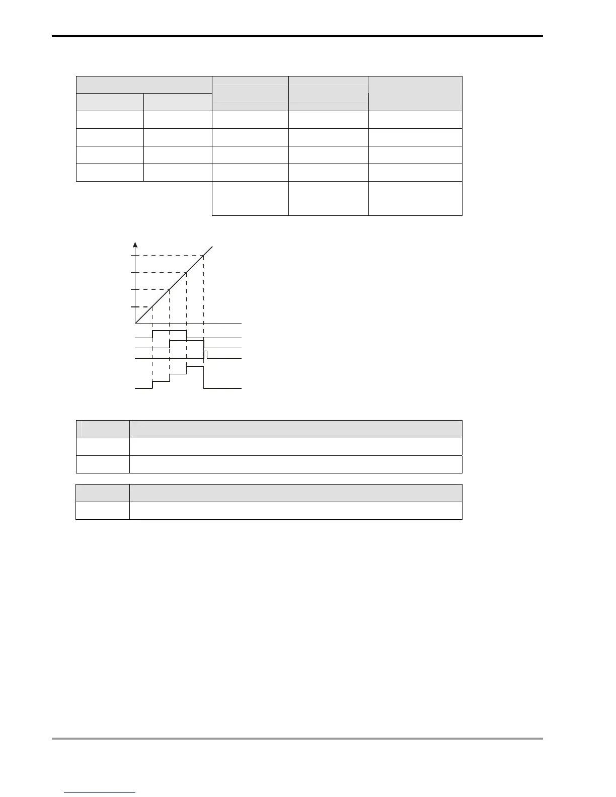
The comparison table:
32-bit data for comparison
High word Low word
No. of Y output On/Off indication
Table counting
register D1150
D1 (K0) D0 (K100) D2 (K10) D3 (K1) 0
D5 (K0) D4 (K200) D6 (K11) D7 (K1) 1
D9 (K0) D8 (K300) D10 (K10) D11 (K0) 2
D13 (K0) D12 (K400) D14 (K11) D15 (K0) 3
K10: Y10
K11: Y11
K0: Off
K1: On
0→1→2→3→0
Cyclic scan
M1151
D1150
Y11
Y10
100
200
300
400
0
1
2
3
0
Present value
in C251
14. Special registers for flags and relevant settings:
Flag Function
M1150 DHSZ instruction in multiple set values comparison mode
M1151 The execution of DHSZ multiple set values comparison mode is completed.
Special D Function
D1150 Table counting register for DHSZ multiple set values comparison mode
Program Example 4:
1. Program Example 4 is only applicable to EH/EH2/SV series MPU.
2. DHSZ and DPLSY instructions are combined for frequency control. If D of DHSZ instruction is a special auxiliary
relay M1152, the present value in the counter will be able to control the pulse output frequency of DPLSY
instruction.
3. In this mode,
- S
1
: start device in the comparison table. S
1
can only designate data register D and can be modified by E and
F. Once this mode is enabled, S
1
will not be changed even the E and F has been changed.
- S
2
: number of group data to be compared. S
2
can only designate K1 ~ K255 or H1 ~ HFF and can be
modified by E and F. Once this mode is enabled, S
2
cannot be changed. If S
2
is not within its range, error
code 01EA (hex) will display and the instruction will not be executed.
- S: No. of high speed counter (designated as C241 ~ C254).