7 Application Instructions API 50-99
DVP-PLC APPLICATION MANUAL
7-69
On
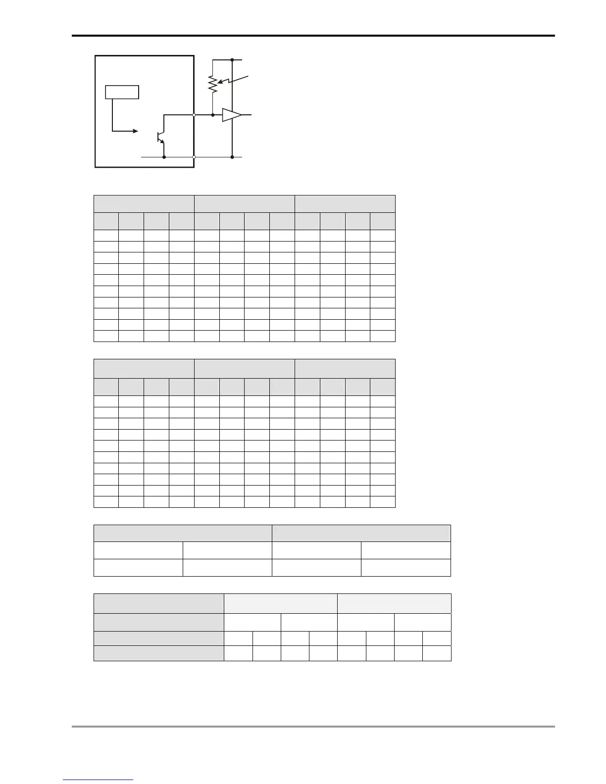
PLC
VCC
Y
Pull-up resistor
Signal output
Drive Y
6. Positive logic (negative polarity) output of BCD code
BCD value Y output (BCDcode) Signal output
b
3
b
2
b
1
b
0
8 4 2 1 A B C D
0 0 0 0 0 0 0 0 1 1 1 1
0 0 0 1 0 0 0 1 1 1 1 0
0 0 1 0 0 0 1 0 1 1 0 1
0 0 1 1 0 0 1 1 1 1 0 0
0 1 0 0 0 1 0 0 1 0 1 1
0 1 0 1 0 1 0 1 1 0 1 0
0 1 1 0 0 1 1 0 1 0 0 1
0 1 1 1 0 1 1 1 1 0 0 0
1 0 0 0 1 0 0 0 0 1 1 1
1 0 0 1 1 0 0 1 0 1 1 0
7. Negative logic (positive polarity) output of BCD code
BCD value Y output (BCDcode) Signal output
b
3
b
2
b
1
b
0
8 4 2 1 A B C D
0 0 0 0 1 1 1 1 0 0 0 0
0 0 0 1 1 1 1 0 0 0 0 1
0 0 1 0 1 1 0 1 0 0 1 0
0 0 1 1 1 1 0 0 0 0 1 1
0 1 0 0 1 0 1 1 0 1 0 0
0 1 0 1 1 0 1 0 0 1 0 1
0 1 1 0 1 0 0 1 0 1 1 0
0 1 1 1 1 0 0 0 0 1 1 1
1 0 0 0 0 1 1 1 1 0 0 0
1 0 0 1 0 1 1 0 1 0 0 1
8. Scan latched signal display
Positive logic (negative polarity) Negative logic (positive polarity)
Y output (latch) Output signal Y output (latch) Output signal
1 0 0 1
9. Settings of n:
Groups of 7-segment display 1 group 2 groups
Y output of BCD code
+ - + -
Scan latched signal display
+ - + - + - + -
n
0 1 2 3 4 5 6 7
+: Positive logic (negative polarity) output -: Negative logic (positive polarity) output
10. The polarity of transistor output and the polarity of the 7-segment display input can be the same or different by
the setting of n.