7 Application Instructions API 50-99
DVP-PLC APPLICATION MANUAL
7-102
0000 0 1 1 111000010
00000000 00010001
D100
D101
Parity
D0 low byte
D0 high byte
D1 low byte
D1 high byte
D2 low byte
D2 high byte
D100
D101
(S) Content of data
K100 = 0 1 1 0 0 1 0 0
K111 = 0 1 1 0 1 1 1 1
K120 = 0 1 1 1 1 0 0 0
K202 = 1 1 0 0 1 0 1 0
K123 = 0 1 1 1 1 0 1 1
K211 = 1 1 0 1 0 0 1 1
K867
0 0 0 1 0 0 0 1
The parity is 1 when there is a odd number of 1.
The parity is 0 when there is a even number of 1.
Tota l
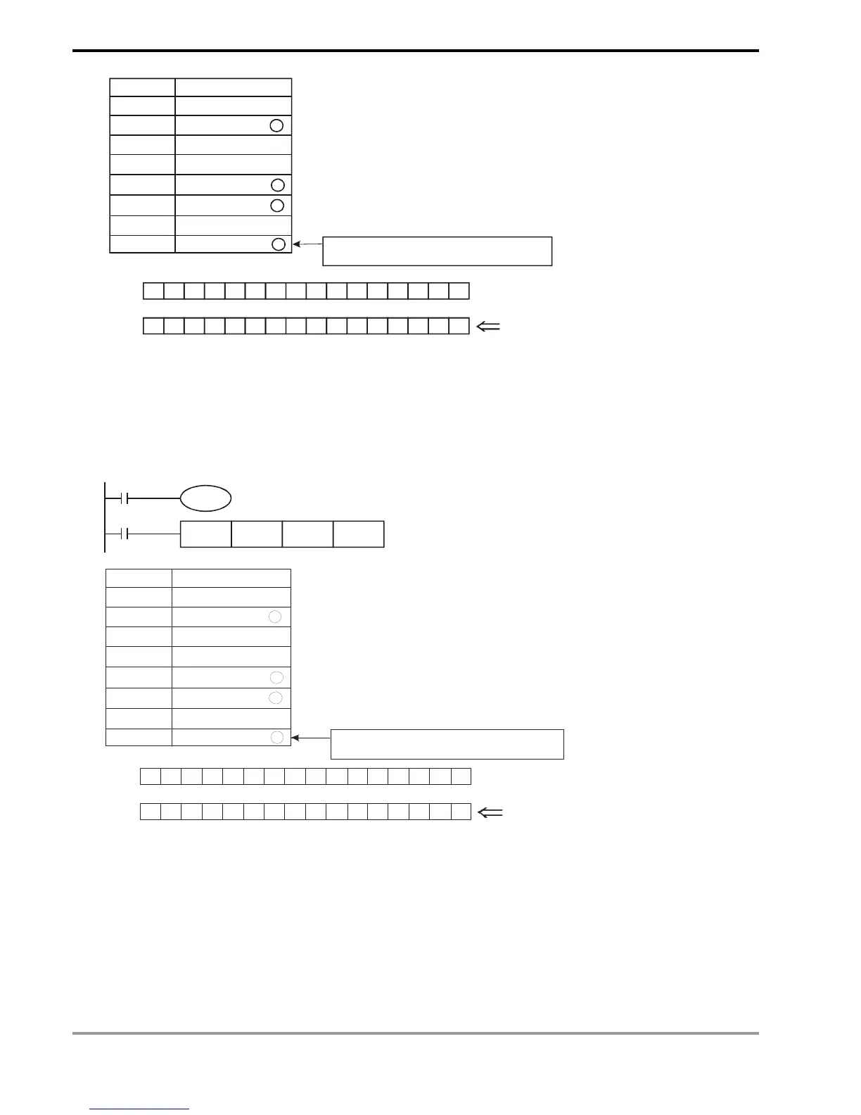
Program Example 2:
1. M1161 = On: The 8-bit conversion mode
2. When X0 = On, the instruction will sum up 6 data stored in the register designated in D0 (8 bits as a unit; n = 6
indicates D0 ~ D5 are designated) and store the result in the register designated in D100. The parity bits are
stored in D101.
X0
CCD D0 D100 K6
M1000
M1161
0000 0 1 1 111000010
0 0000 0 0 0 0 0010001
D100
D101
Parity
D0 low byte
D1 low byte
D2 low byte
D3 low byte
D4 low byte
D5 low byte
D100
D101
(S) Content of data
K100 = 0 1 1 0 0 1 0 0
K111 = 0 1 1 0 1 1 1 1
K120 = 0 1 1 1 1 0 0 0
K202 = 1 1 0 0 1 0 1 0
K123 = 0 1 1 1 1 0 1 1
K211 = 1 1 0 1 0 0 1 1
K867
0 0 0 1 0 0 0 1
The parity is 1 when there is a odd number of 1.
The parity is 0 when there is a even number of 1.
Total