8 Application Instructions API 100-149
DVP-PLC Application Manual
8-3
Register DATA Explanation
D1079 low ‘0’ 30 H
D1079 high ‘0’ 30 H
D1080 low ‘0’ 30 H
D1080 high ‘0’ 30 H
Content of
address 2104 H
PLC automatically convert
ASCII codes to numerals
and store the numeral in
D1053 = 0000 H
D1081 low ‘0’ 30 H
D1081 high ‘1’ 31 H
D1082 low ‘3’ 33 H
D1082 high ‘6’ 36 H
Content of
address 2105 H
PLC automatically convert
ASCII codes to numerals
and store the numeral in
D1054 = 0136 H
D1083 low ‘0’ 30 H
D1083 high ‘0’ 30 H
D1084 low ‘0’ 30 H
D1084 high ‘0’ 30 H
Content of
address 2106 H
PLC automatically convert
ASCII codes to numerals
and store the numeral in
D1055 = 0000 H
D1085 low ‘3’ 33 H LRC CHK 1
D1085 high ‘B’ 42 H LRC CHK 0
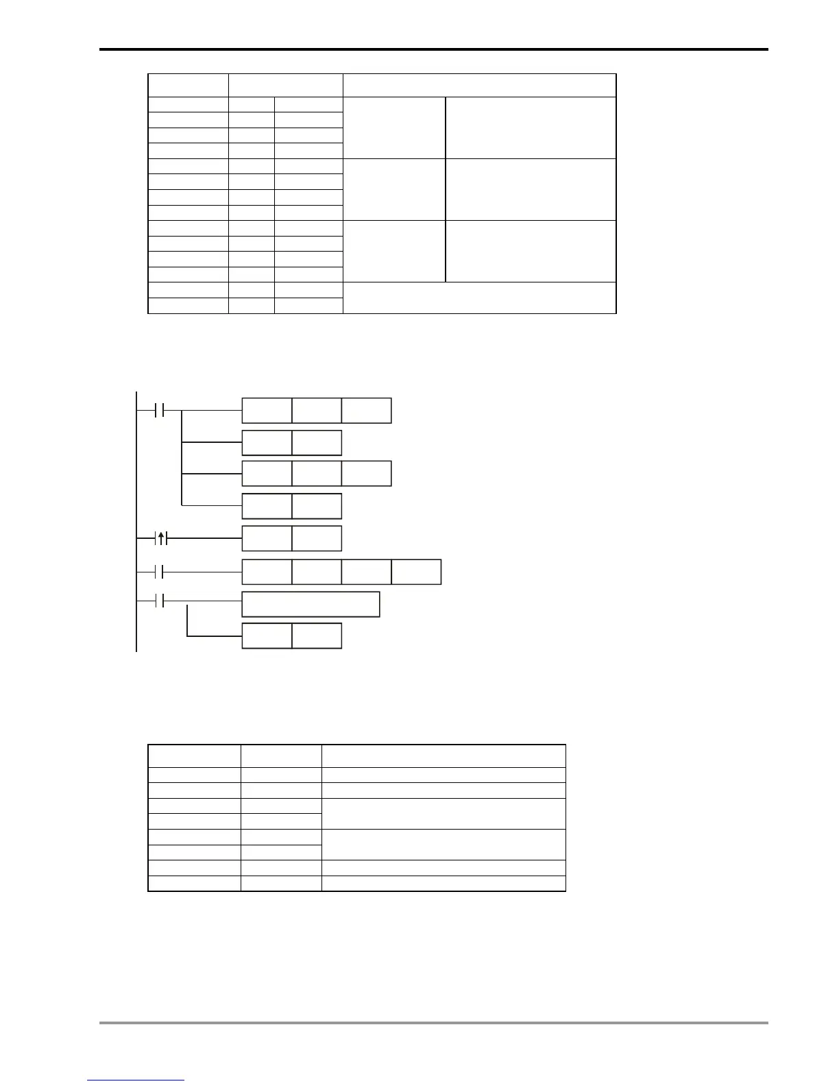
Program Example 2:
Communication between PLC and VFD-S series AC motor drives (RTU Mode, M1143 = On)
MOV D1120H87
M1002
SET M1120
MOV
D1129K100
M1127
RST M1127
receiving
completed
Set up communication protocol 9600, 8, E, 1
Retain communication protocol
Set up communication time-out: 100ms
Process of receiving data
Sending/receiving of data is completed.
The flag is reset.
SET M1122
Set up as sending flag
X0
The received data in hex are stored in D1070 ~ D1085.
SET M1143
Set up as RTU mode
X0
MODRD K1 H2102
Set up communication instruction
device address 01 data address H2102
data length 2 words
K2
PLC VFD-S, PLC sends: 01 03 2102 0002 6F F7
VFD-S PLC, PLC receives: 01 03 04 1770 0000 FE 5C
Registers for sent data (sending messages)
Register DATA Explanation
D1089 low 01 H Address
D1090 low 03 H Function
D1091 low 21 H
D1092 low 02 H
Starting data address
D1093 low 00 H
D1094 low 02 H
Number of data (counted by words)
D1095 low 6F H CRC CHK Low
D1096 low F7 H CRC CHK High