8 Application Instructions API 100-149
DVP-PLC Application Manual
8-18
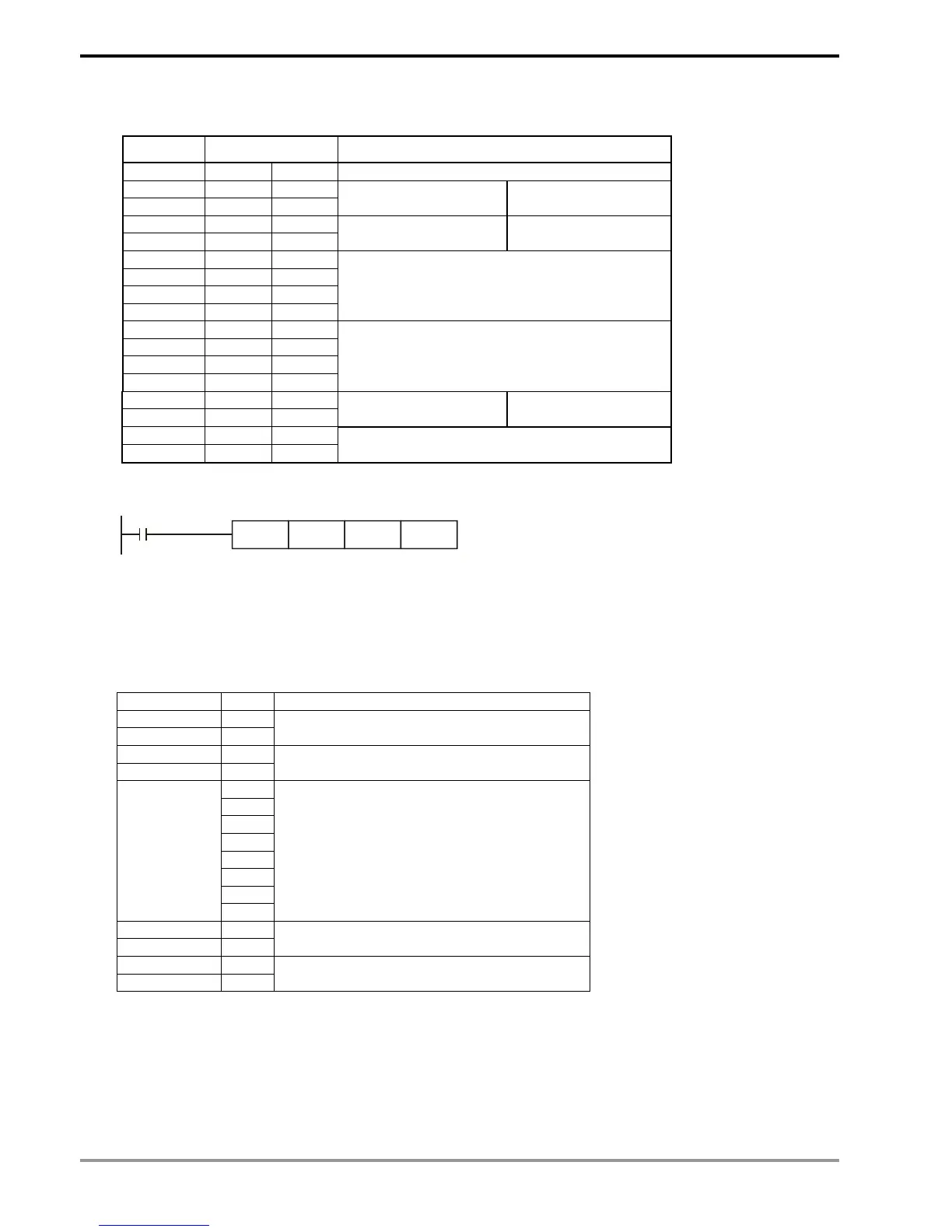
PLC VFD-S, PLC sends: “: 01 03 2101 0006 D4 CR LF ”
Registers for sent data (sending messages)
Register DATA Explanation
D100 low ‘: ’ 3A H STX
D101 low ‘0’ 30 H ADR 1
D102 low ‘1’ 31 H ADR 0
Address of AC motor
drive: ADR (1,0)
D103 low ‘0’ 30 H CMD 1
D104 low ‘3’ 33 H CMD 0
Instruction code: CMD
(1,0)
D105 low ‘2’ 32 H
D106 low ‘1’ 31 H
D107 high ‘0’ 30 H
D108 low ‘1’ 31 H
Starting data address
D109 low ‘0’ 30 H
D110 low ‘0’ 30 H
D111 low ‘0’ 30 H
D112 low ‘6’ 36 H
Number of data (counted by words)
D113 low ‘D’ 44 H LRC CHK 1
D114 low ‘4’ 34 H LRC CHK 0
Error checksum: LRC
CHK (0,1)
D115 low CR A H
D116 low LF D H
END
The error checksum LRC CHK (0,1) can be calculated by LRC instruction (in 8-bit mode, M1161 = On).
M1000
LRC D101 K12 D113
LRC checksum: 01 H + 03 H + 21 H + 01 H + 00 H + 06 H = 2C H. Obtain 2’s complement, D4H, and store ‘D’(44H) in
the lower 8 bits of D113 and ‘4’(34H) in the lower 8 bits of D114.
Remarks:
1. The format of ASCII mode with a communication datum
STX ‘: ’ Start word = ‘: ’ (3AH)
Address Hi ‘ 0 ’
Address Lo ‘ 1 ’
Communication:
8-bit address consists of 2 ASCll codes
Function Hi ‘ 0 ’
Function Lo ‘ 3 ’
Function code:
8-bit function consists of 2 ASCll codes
‘ 2 ’
‘ 1 ’
‘ 0 ’
‘ 2 ’
‘ 0 ’
‘ 0 ’
‘ 0 ’
DATA (n-1)
…….
DATA 0
‘ 2 ’
Data content:
n × 8-bit data consists of 2n ASCll
codes
LRC CHK Hi ‘ D ’
LRC CHK Lo ‘ 7 ’
LRC checksum:
8-bit checksum consists of 2 ASCll codes
END Hi CR
END Lo LF
End word:
END Hi = CR (0DH), END Lo = LF(0AH)
2. LRC checksum: 2’s complement of the summed up value of communication address and data. For example,
01 H + 03 H + 21 H + 02 H + 00 H + 02 H = 29 H. Obtain 2’s complement = D7H.