9 Application Instructions API 150-199
DVP-PLC Application Manual
9-80
7. When the 2-axis synchronous motion instruction is enabled, the start frequency and acceleration/deceleration
time in Y axis will be same as the settings in X axis.
8. The number of output pulses for the 2-axis motion shall not be the values within 1 ~ 59; otherwise the line drawn
will not be straight enough.
9. There is no limitation on the number of times using the instruction. However, assume CH1 or CH2 output is in use,
the 1
st
group X/Y axis will not be able to output. If CH3 or CH4 output is in use, the 2
nd
group X/Y axis will not be
able to output.
Program Example:
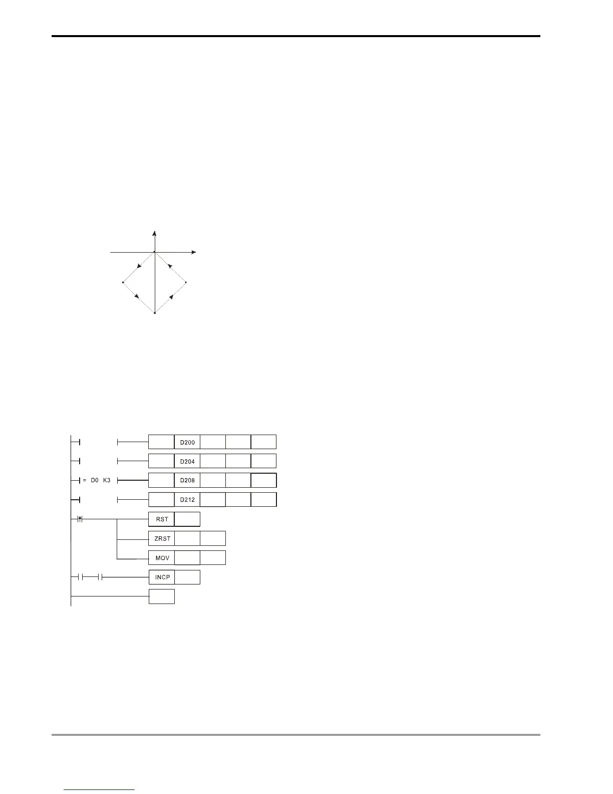
1. Draw a rhombus as the figure below.
(0,0)
(-27000,-27000)
(0,-55000)
(27000,-27000)
X
Y
2. Steps:
a) Set the four coordinates (0,0), (-27000, -27000), (0, -55000), (27000, -27000) (as the figure above). Place them in
the 32-bit (D200, D202), (D204, D206), (D208, D210), (D212, D214).
b) Write program codes as follows.
c) PLC RUN. Set M0 as On and start the 2-axis line drawing.
D214DPPMA
D210DPPMA
D206DPPMA
K100000
D202DPPMA Y0
= D0 K1
= D0 K2
= D0 K4
K100000
Y0
K100000
Y0
K100000
Y0
M1029
END
M0
K1 D0
D0
M0 M1029
D1336 D1339
3. Motion explanation:
When PLC RUN and M0 = On, PLC will start the first point-to-point motion by 100KHz. D0 will plus 1 whenever a
point-to-point motion is completed and the second point-to-point motion will start to execute automatically. The
same motion will keep executing until the fourth point-to-point motion is completed.