9 Application Instructions API 150-199
DVP-PLC Application Manual
9-82
(0,0)
X
Y
(0,0)
X
Y
(S ,S )
12
(S ,S )
12
1
0
s
e
g
m
e
n
t
s
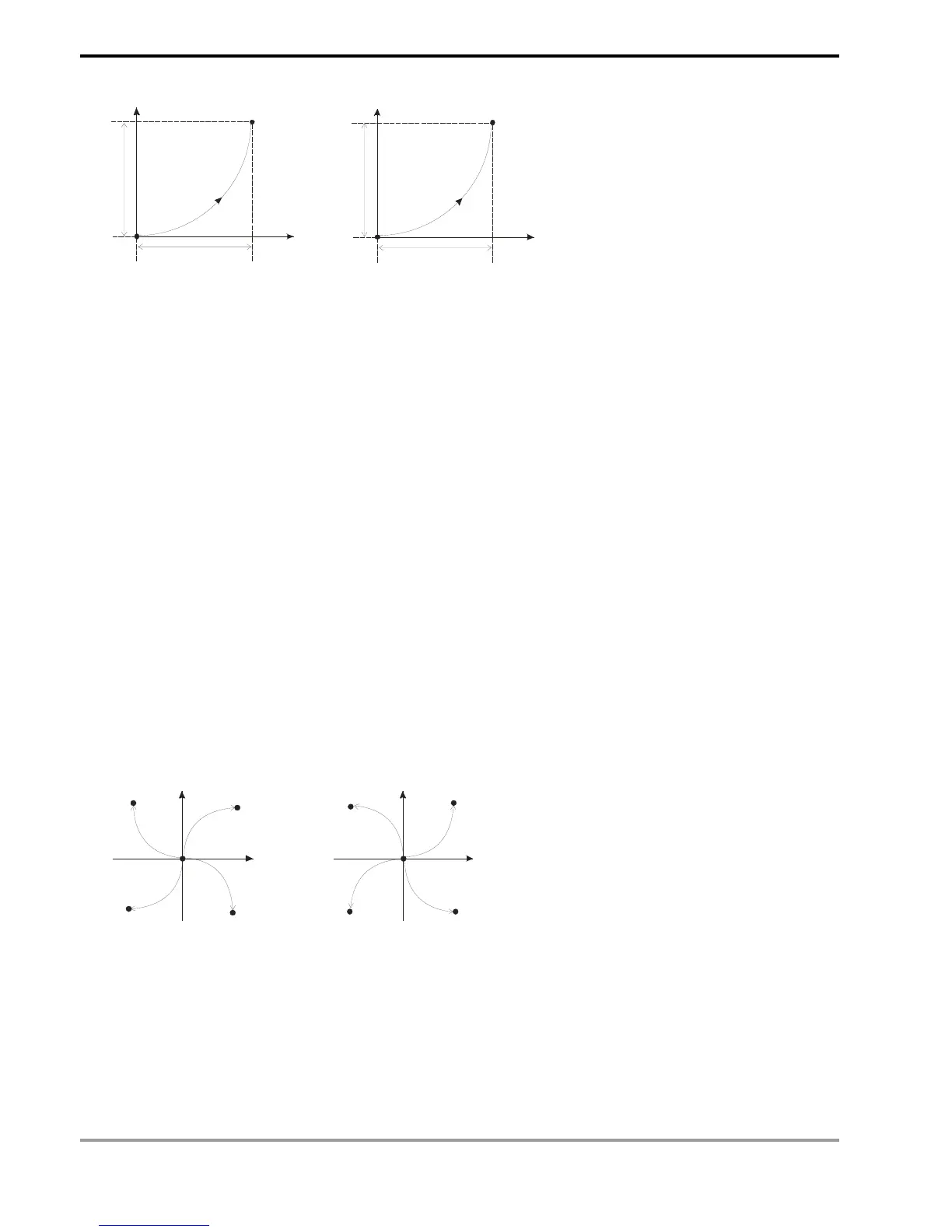
10 segments
2
0
s
e
g
m
e
n
t
s
20 segments
Figure 3
Figure 4
6. D can designate Y0 and Y4.
When Y0 is designated:
Y0 refers to 1
st
group X-axis pulse output device.
Y1 refers to 1
st
group X-axis direction signal.
Y2 refers to 1
st
group Y-axis pulse output device.
Y3 refers to 1
st
group Y-axis direction signal.
When Y4 is designated:
Y4 refers to 2
nd
group X-axis pulse output device.
Y5 refers to 2
nd
group X-axis direction signal.
Y6 refers to 2
nd
group Y-axis pulse output device.
Y7 refers to 2
nd
group Y-axis direction signal.
When direction signal outputs, Off will not occur immediately after the pulse output is over. Direction signal will
turn Off when the drive contact is Off.
7. Draw four 90° arcs.
8. When the direction signal is On, the direction is positive. When the direction signal is Off, the direction is negative.
When S is set as K0, K2, the arcs will be clockwise (see figure 5). When S is set as K1, K3, the arcs will be
counterclockwise (see figure 6).
Y
X
Y
X
Quadrant I
Quadrant II
Quadrant III
Quadrant IV
Quadrant I
Quadrant II
Quadrant III
Quadrant IV
Figure 5 Figure 6
9. When the 2-axis motion is being executed in 10 segments (of average resolution), the operation time of the
instruction when the instruction is first enabled is approximately 5ms. The number of output pulses cannot be less
than 100 and more than 1,000,000; otherwise, the instruction cannot be enabled.
10. When the 2-axis motion is being executed in 20 segments (of high resolution), the operation time of the
instruction when the instruction is first enabled is approximately 10ms. The number of output pulses cannot be
less than 1,000 and more than 10,000,000; otherwise, the instruction cannot be enabled.