5 Categories and Use of Basic Application Instructions
DVP-PM Operation Instruction
5-20
API Mnemonic Function
07
WDT P Watchdog Timer Refresh
Controllers
20PM 10PM
OP Descriptions Program Steps
N/A
No operand. No contact to drive the instruction is required
WDT, WDTP: 1 step
Explanations:
1. WDT instruction can be used to reset the Watch Dog Timer. If the PLC scan time (from address 0 to END or
FEND instruction) is more than 200ms, the ERROR LED will flash. In this case, users have to turn the power
OFF and then ON to clear the fault. PLC will determine the status of RUN/STOP according to RUN/STOP
switch. If there is no RUN/STOP switch, PLC will return to STOP status automatically.
2. Time to use WDT:
a) When error occur in PLC system.
b) When the scan time of the program exceeds the WDT value in D1000. It can be modified by using the following
two methods.
i. Use WDT instruction
T1
T2
STEP0 END(FEND)
WDT
ii. Use the set value in D1000 (Default: 200ms) to change the time for watchdog.
Points to note:
1. When the WDT instruction is used it will operate on every program scan as long as its input condition has been
made. To force the WDT instruction to operate for only ONE scan, users have to use the pulse (P) format of
the WDT instruction, i.e. WDTP.
2. The watchdog timer has a default setting of 200ms. This time limit can be customized to users requirement by
editing the content in D1000, the wathdog timer register.
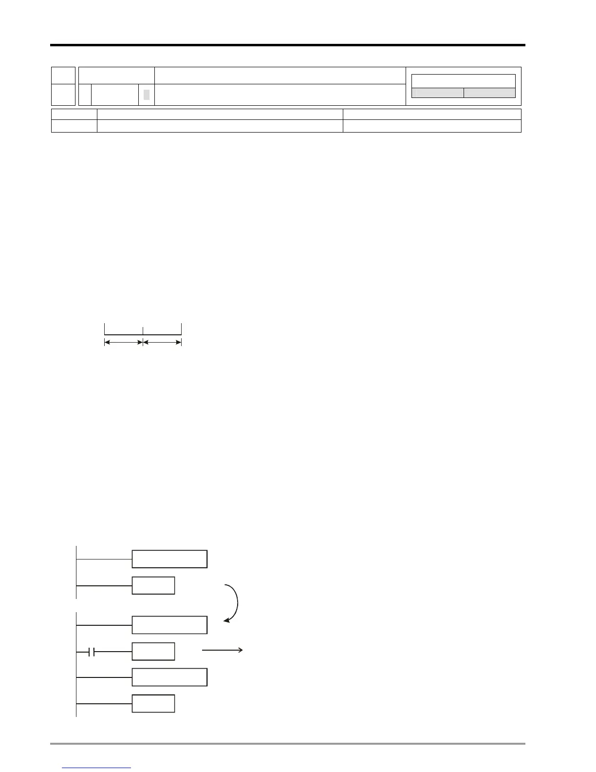
Program example:
If the program scan time is over 300ms, users can divide the program into 2 parts. Insert the WDT instruction in
between, making scan time of the first half and second half of the program being less than 200ms.
X0
END
END
WDT
300ms program
150ms program
150ms program
Dividing the program to two parts
so that both parts scan time are
less than 200ms.
Watchdog timer reset

 Loading...


