13 CANopen Communication Card
DVP-PM Application Manual
13-9
during SDO data transmission, the error code will be stored in CR#073 and CR#074. If CR#073~CR#076 are
used at one time, CR#073 serves as LSB and CR#076 as MSB.
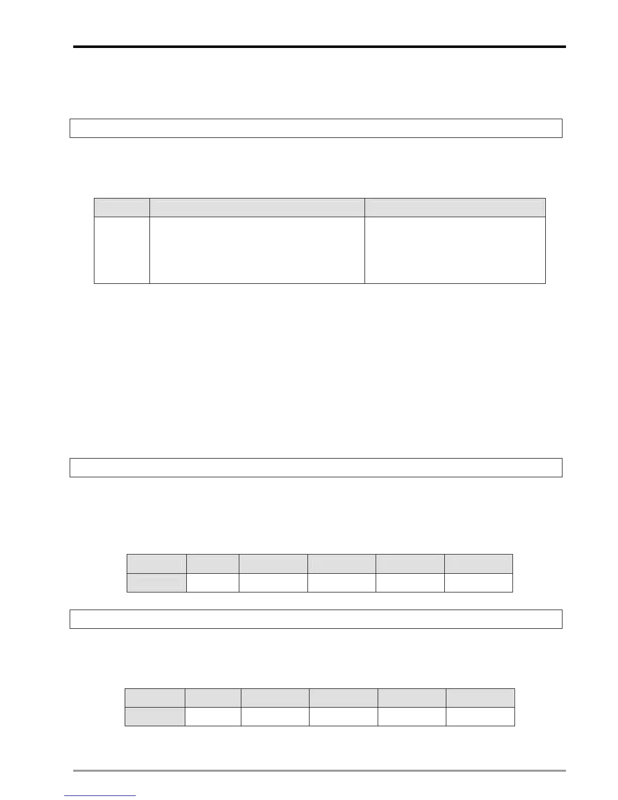
CR#080: NMT command
[Explanations]
When DVP-FPMC is Master, NMT commands can be used to change the network status. Please refer to the table
below for the setting format.
Bit b15~b8 b7~b0
Function
Network management command
1: enable node communication
2: disable node communication
128: switch the operation mode
129: reset node communication
Node ID of Slave
Parameters for A2 mode
A2 mode is one of the applications of DVP-FPMC specifically for delta servo drive: ASDA-A2. In A2 mode, there
are 4 CANopen nodes ID1~ID4 planned for ASDA-A2, and control registers CR#100~CR#499 corresponding to
servo parameters. CR#100~CR#199 are CRs for Node ID1, CR#200~CR#299 are CRs for Node ID2,
CR#300~CR#399 are CRs for Node ID3, CR#400~CR#499 are CRs for Node ID4. Care should be taken on the
special index “n” in the CR number. The value of index n could be 1, 2, 3 or 4 indicates 100, 200, 300 or 400
corrensponding to the 4 CANopen nodes for ASDA-A2. Control registers for ASDA-A2 application are applicable
only in A2 mode.
CR#010: CANopen bus scan
[Explanations]
Scan CANopen nodes ID1~ID4. b0~b3 of CR#010 correnpond to node1~node4. When the bit is 1, the
corresponding node will be scanned and the content of the register will be cleared automatically. Please refer to
the table below.
Bit b15~b4 b3 b2 b1 b0
Node ID Reserved Node 4 Node 3 Node 2 Node 1
CR#020: CANopen bus communication status
[Explanations]
Display the node communication status by 2 consecutive bits: 00: disconnected, 01: connected, 11: ready. Please
refer to the table below.
Bit b15~b8 b7~b6 b5~b4 b3~b2 b1~b0
Node ID Reserved Node 4 Node 3 Node 2 Node 1

 Loading...


