9 Electrical CAM
DVP-PM Application Manual
9-16
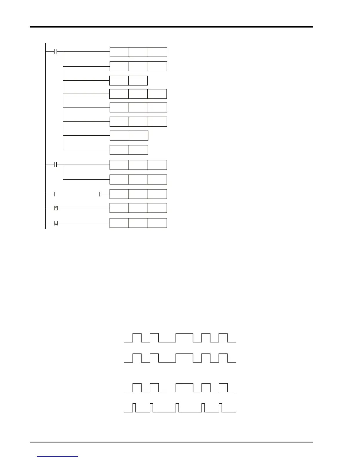
MOV
K2
D1832
M1002
ZRST
D1860 D1863
M1002
SET M1035
DMOV K2000
D1920
MOV
H10
D1926
MOV H4000 D1846
ZRST D1848 D1849
Set up pulse input/output type
as A/B phase D=H30
Set up D1799 (input terminal polarity setting)= 6.
MPGA0/MPGB0 are NO contacts.
MOV H30 D1816
MOV K6 D1799
RST M1746
MOV H0 D1846
M0
M0
LD= D1846 H4000
Set up operation speed of Y axis
variable speed operation
When D1846=H4000, Y axis variable speed
operation executes.
When M0 is rising-edge triggered, set
D1846=H4000 to enable acyclic E-CAM
Reset M1746. Acyclic E-CAM is triggered by
START0
Enable STOP0/START0 as external input point
When M0 is falling -edge triggered, acyclic E-CAM
stops
Repeat E-CAM Data for 2 times
ZRST
D1860 D1863
K200
D1864
MOV
RST
D1868
9.3 Explanations on Special Flags and Registers
E-CAM max frequency: DD1840, M1749
1. D1841, D1840 (VI): E-CAM max frequency. If the registers are not set up properly, output function will
not operate normally.
2. M1749: E-CAM max frequency control
M1749 = OFF, the Slave frequency will follow the Master frequency, but the max frequency will be
300kHz.
Master
Slave
M1749 = ON, the max frequency of Slave will be specified by D1841, D1840(VI)
Master
Slave
Enabling cyclic E-CAM / Completion of cyclic E-CAM: D1846 / M1813

 Loading...


