9 Electrical CAM
DVP-PM Application Manual
9-15
Application Example
Setup
:
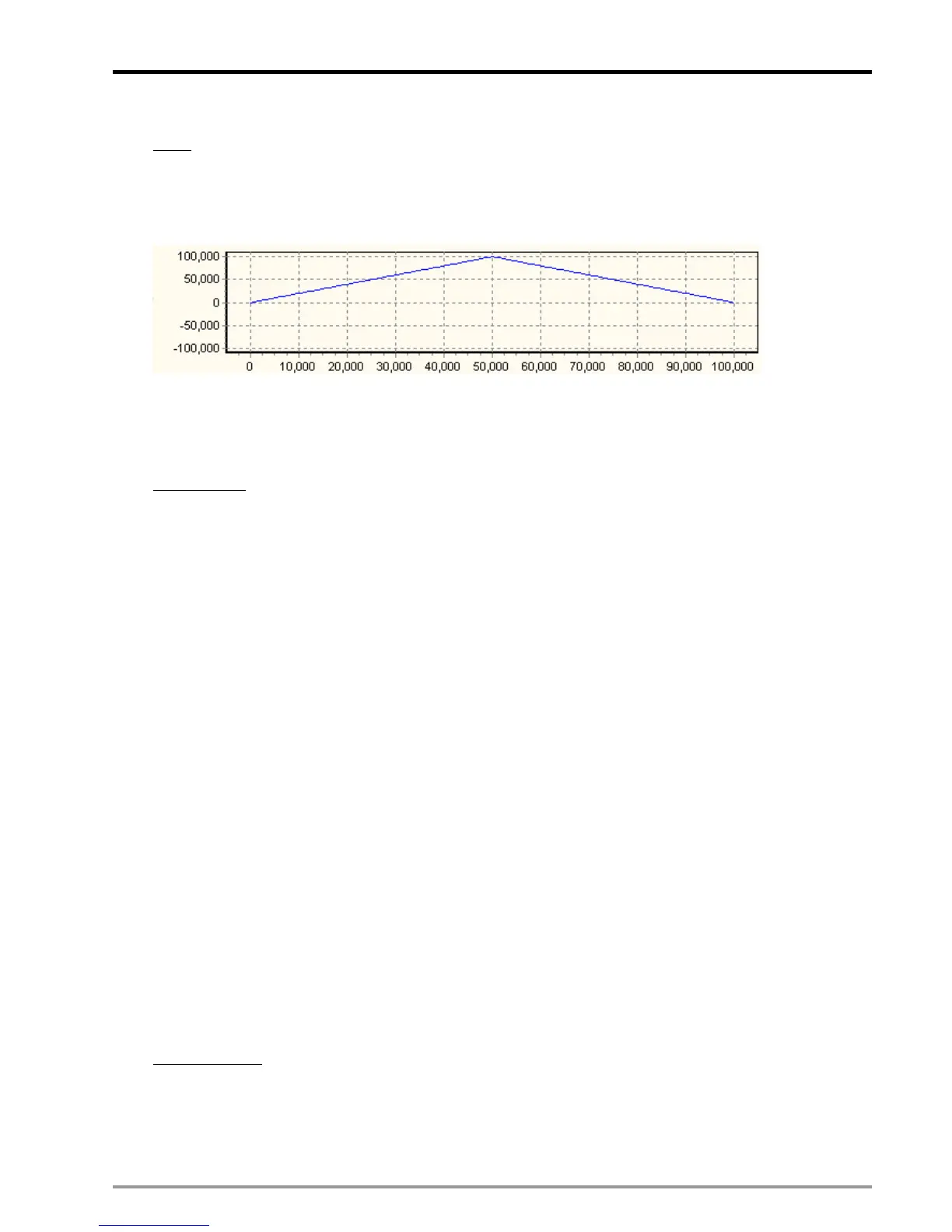
Set up E-CAM Data as below:
E-CAM cycle: Master position 0~100000; Control unit: motor system;
Every time when START0 is triggered, execute 3 acyclic E-CAM Data (D1832 = 2)
Set up E-CAM Data as the above curve. E-CAM Data can be set up by PMSoft or DTO instruction (Please
refer to explanations in 9.4). Connect pulse output terminals (FP+, FP-, RP+, RP-) to X axis MPG input
terminals (A0+, A0-, B0+, B0-). In this case, input signals are from output signals of Y axis.
Control Steps:
Step 1: Initialization
(1) Clear the content in registers D1848, D1849, D1862, D1863, D1868.
(2) Set up input pulse type as A/B phase (D1864 = H200)
(3) Set up pulse output type of Y axis as A/B phase (D1896 = H30)
(4)
Set up D1799 (input terminal polarity setting) = 6, MPGA0 and MPGB0 are NO contacts
(5) Set M1035 = ON to enable STOP0/START0 as external input point
(6) Set M1746 = OFF to enable START0 as the start signal of acyclic E-CAM.
(7) Set D1832 = 2 (Repeat E-CAM Data for two times)
(8) Set up operation speed of Y axis variable speed operation (in this case Y axis outputs signals as
Input signals of Master).
Step 2: Set On M0 to enable acyclic E-CAM.
When D1846=H4000, Y axis variable speed operation is enabled but X axis is not yet executed.
Step 3: Trigger START0.
X axis will be activated and executes the E-CAM data for 3 cycles.
Step 4: Reset M0.
When M0 is reset during the execution of E-CAM, X axis will be stopped.
Ladder Diagram:

 Loading...


