3 Functions of Devices in DVP-PM
DVP-PM Application Manual
3-8
1. General auxiliary relay: If the relay encounters power OFF during the operation of DVP-PM, its status will be
reset to OFF and remains OFF when the power is ON again.
2. Latched auxiliary relay: If the relay encounters power OFF during the operation of DVP-PM, its status will be
retained and resumes the status when the power is ON again.
3. Special auxiliary relay: Every relay of this kind has its specific function. DO NOT use undefined special purpose
auxiliary relay. See 3.10 for special relay and special registers and 3.11 for their functions.
3.5 Numbering and Functions of Step Relays [S]
No. of step relay (in decimal):
General purpose
S0 ~ S499, 490 points, can be modified as latched area by setting up
parameters.
Step relay
S
Latched
S500 ~ S1023, 524 points, can be modified as non-latched area by
setting up parameters.
Total 1,024
points
Functions of step relays:
The device No. of S is S0 ~ S1023 (total 1,024 points). Both step relay S and output relay Y have output coils and NO,
NC contacts, and there is no limitation on the times of using the contacts. You can use auxiliary relay M in the
program but it cannot directly drive the external load. Step relay can be used as general auxiliary relays.
3.6 Numbering and Functions of Timers [T]
No. of timers (in decimal):
Timer
T
10ms general purpose
T0 ~ T255, 256 points, can be modified as latched area by setting up
parameters.
Functions of timers:
The timer resolution is 10ms and counts up when activated. The associated contacts of timer will be driven when the
current value reaches the set value in timer. Set value can be K value (decimal) or D register.
The actual set time in the timer = timer resolution × set value
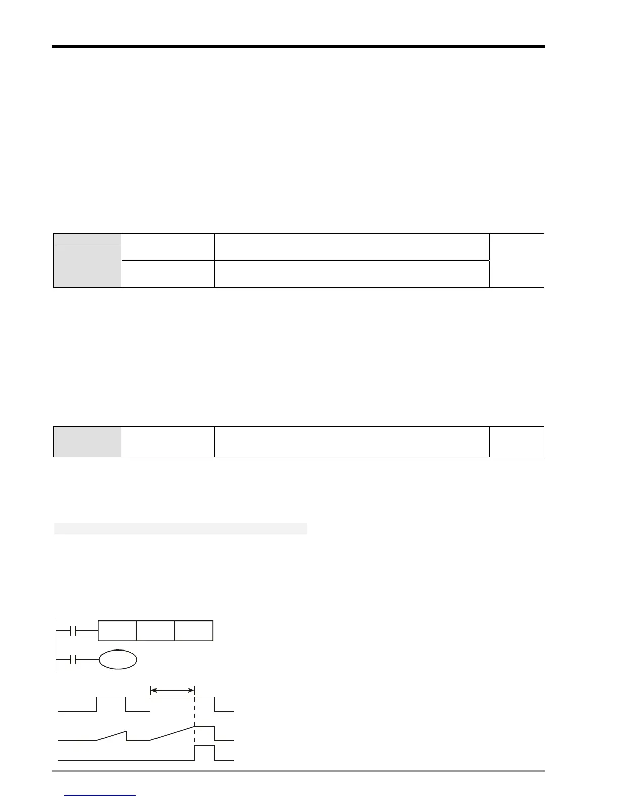
General purpose timer:
General timer counts once when TMR instruction is driven once. When TMR instruction is executed and the present
value reaches the set value, the associated output coil will be ON.
T0
Y0
X0
TMR T0 K100
X0
T0
Y0
PV
SV = K100
1 sec
When X0 = ON, The PV in timer T0 will count up with
timer resolution 10ms. When the PV = SV (K100), the
output coil T0 will be ON.
When X0 = OFF or the power is OFF, the PV in timer
T0 will be cleared as 0, and the output coil will be OFF.

 Loading...


