14 High Speed Compare and Capture
DVP-PM Application Manual
14-8
14.3 Capture Function
Reading current position of X/Y/Z axis or count value of C200/C204 in program scan results in error due to the
program scan time. To avoid the error, we can use Capture function to read data immediately through external
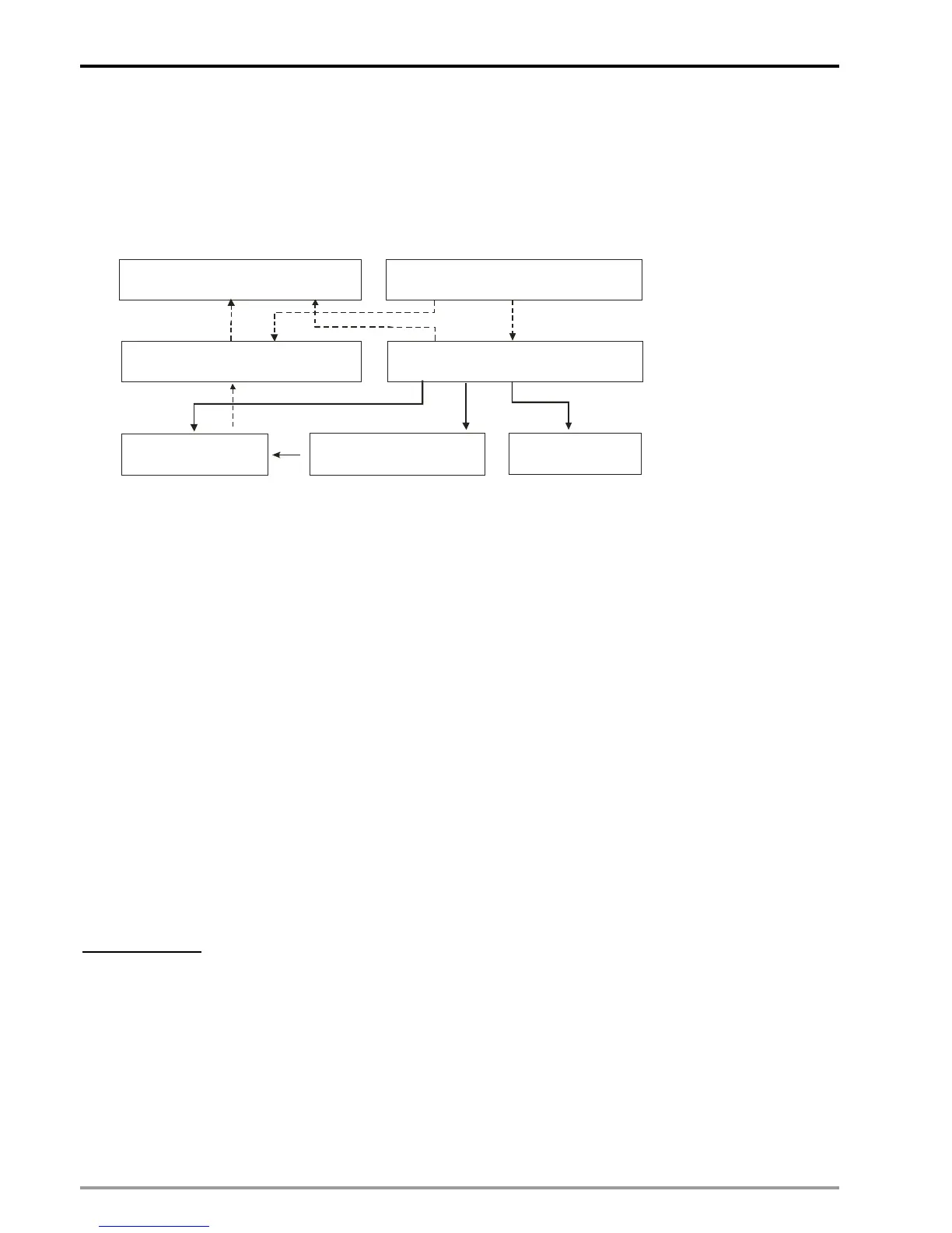
input signal. The Capture function is illustrated as the below diagram.
(G)FROM K253 K1 D0 D50
(A)TO K253 K1 D0 D50
(C)Data register DRn(n=0~7)
(B)Control register CRn(n=0~7)
(D)Data source for
Capture function
(E)Capture function
Bit 5-4=0
(F)Trigger switch of
Capture function
Block A: Use TO instruction to write data into control registers (Block B) and data registers (Block C).
Block B: According to the data specified by TO instruction, control registers set up the data source (Block D),
enable the Capture function (Block E) and select the trigger switch (Block F).
Block C: Data registers store the data specified by TO instruction or the caught value from the data source
specified in Block D.
Block D: There are 5 sets of data source including current position of X/Y/Z axis, count value of C200
(current position of Master / MPG of X-axis) and count value of C204 (MPG of Y-axis). For settings
of high speed counters C200 and C204, please refer to Ch3 of this manual.
Block E: Enable Capture function
Block F: Select trigger switch of Capture function
Block G: Use FROM instruction to read data from control registers (Block B) and data registers (Block C)
which stores the caught value.
Process of Capture function:
Write in settings of Capture function by TO instruction (Block A). Æ External input signal triggers ON (Block F) Æ
Capture the value from Block D and store the caught data in Block C Æ Read the caught data by FROM
instruction (Block G).
Program example:
In this example high speed counter C204 is used and high speed counting is enabled. Trigger signal is set as
DOG0 to capture the count value of C204 when MPG is rotating. Please see below for the example program.

 Loading...


