9 Electrical CAM
DVP-PM Application Manual
9-53
Ladder Diagram
:
SET M1757
DSUB
D1862
D306
D350
DMOV K10005
D0
DFROM
K100
D0 D300
K5
Slave position
Accumulated
Master position
M1000
M1812
Completion of E-CAM initialization
M1792 X1
Operation command
bit1 (START)
OX, X-axis Ready
Master
position
Tar g et
position
Limit switch
LD= D1846
H2000
DLD> D350
D1842
Master position
in current cycle
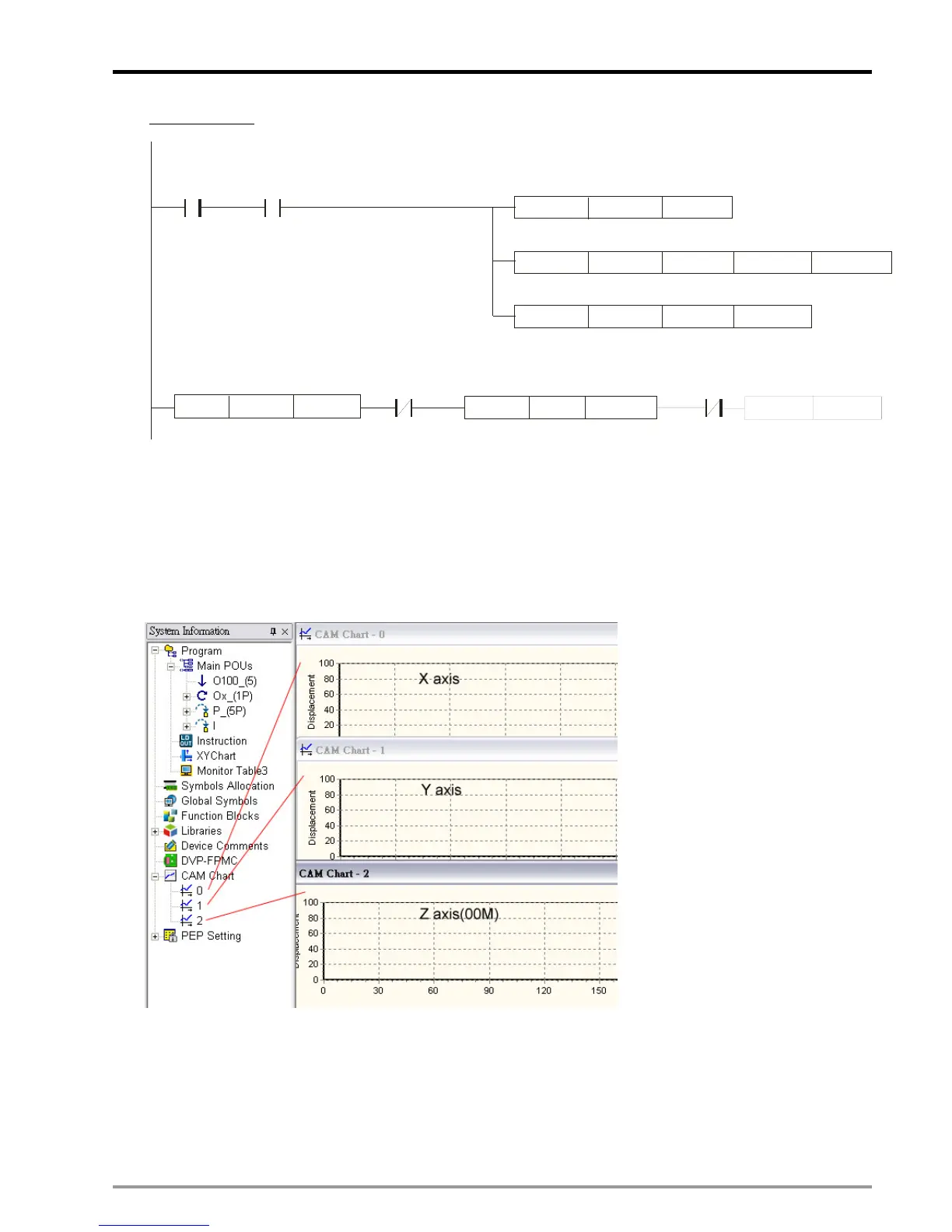
9.5 Multi-axis E-CAM
Single-axis E-CAM can be executed in cyclic operation and acyclic operation. Unlike single-axis E-CAM,
multi-axis E-CAM can only be executed in cyclic operation. For multi-axis E-CAM, only one set of E-CAM Charts
can be applied, i.e. CAM Chart 0 ~ CAM Chart 2 correspond to X, Y, Z axis.
Same as single-axis cyclic E-CAM, multi-axis E-CAM is enabled by setting b13 of D1846 as ON. In addition to
setting D1846, work modes of each axis should also be set up and enabled, and C200 should be activated for
counting pulses of Master.
1. D1846
Set b13 of D1846 as ON (D1846 =H’2000) to enable multi-axis E-CAM.

 Loading...


