9 Electrical CAM
DVP-PM Application Manual
9-54
2. Set up work modes (X-D1847 Y-D1927 Z-D2007)
For multi-axis E-CAM, b12 and b11 of D1847 should be set as 01 (bit11=1). When Y, Z axis are applied, bit11
of D1927 and D2007 should also be set as 1.
3. C200/C204 counter
Enable C200/C204 after setting up counting mode of C200/C204. Multi-axis E-CAM applies C200/C204 as
the input signal of Master. Counting mode of C200/C204 should match the pulse input pattern of Master.
C200/C204 counting mode setting:
Device C200 Counting Mode Device C204 Counting Mode
M1200=0, M1201=0 U/D* M1204=0, M1205=0 U/D
M1200=1, M1201=0 P/D* M1204=1, M1205=0 P/D
M1200=0, M1201=1 A/B*(Single frequency) M1204=0, M1205=1 A/B(Single frequency)
M1200=1, M1201=1 4A/B(Quadruple frequency) M1204=1, M1205=1 4A/B(Quadruple frequency)
Deivce C200 Counting Mode Device C204 Counting Mode
M1203=1 PG0 M1207=1 PG1
Note:
z U/D: Counting up / Counting down, P/D: Pulse / Direction, A/B: A-phase / B-phase
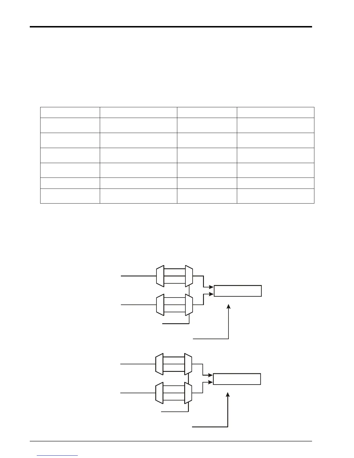
z M1908: Input signal control of C200 / C204
When M1908 = OFF, the input signal of C200 is controlled by MPG A0/B0 and reset signal is controlled by
PG0. In addition, Input signal of C204 is controlled by MPG A1/B1 and reset signal is controlled by PG1.
C200
C200
reset signal
Counting mode selection
Input pulse
Input pulse
Puls

 Loading...


