9 Electrical CAM
DVP-PM Application Manual
9-55
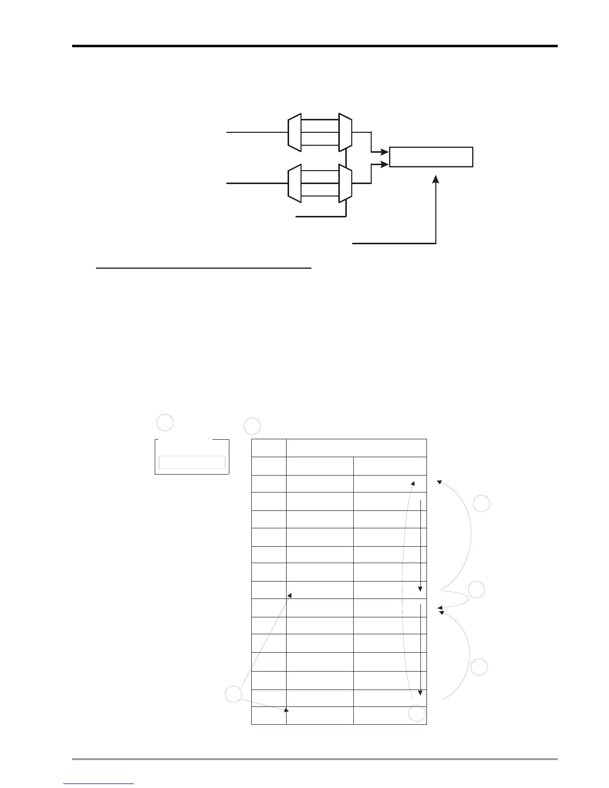
When M1908 = ON, the 3 axes X/Y/Z share the same high speed counter C200. The input signal of C200 is
controlled by MPG A0/B0. C200 reset signal is controlled by PG0.
C200
C200
reset signal
Counting mode selection
Input pulse
Input pulse
Pulse
U
A
B
Dir
PV of C200
D
M1200/M1201
MPGB0
MPGA0
M1203=1, PG0
There are 2 execution patterns of multi-axis E-CAM:
1. Point-to-point Switching Pattern
In multi-axis E-CAM, we can separate an M-points E-CAM Data into several sections for realizing real-time
CAM data switching between sections. Only one section will be executed for one time and users can add
new data into the next section. For switching to next section, insert an additional point of (0, n1) between the
sections. When Master position is detected as 0, set value n1 of Slave position will be the target number for
poin-to-point switching. When single section is completed, M1813/M1893/M2053 will be ON and has to be
clear by user for Indicating next completion. In the below diagram we use an N-point E-CAM Data and
separate the beginning 202 points into 2 sect.ions.
No.
0
1
2
...
98
99
100
101
102
198
199
200
201
...
0
0
...
...
...
...
E-CAM X-axis
Master
Slave
M0
M1
M98
M99
M101
M103
M199
M200
M102
M2
S0
S1
S2
S98
S99
0or101
S101
S102
S103
S199
S200
101or 0
When
M100=0,
S100=0
When
M100=0,
S100=101
When
M201=0,
S201=101
When
M201=0,
S201=

 Loading...


