9 Electrical CAM
DVP-PM Application Manual
9-56
Set value of Slave in No.100 and No.201 indicates the target number for next execution. Therefore, before
the switching point is reached users can insert or modify the data in the next section. However, care should
be taken on setting the starting value of the second section. For second section, if the starting value of
Master (M101) is set as 0, Slave will continue the execution based on the ending value of previous section,
i.e. the starting value will be Master position: M99+M102, and Slave position: S99+S101.On the other hand,
if the starting value of Master is not “0”, the starting value of Slave will be based on “0”, i.e. Master position:
M99+M102 and Slave position: 0+S101.
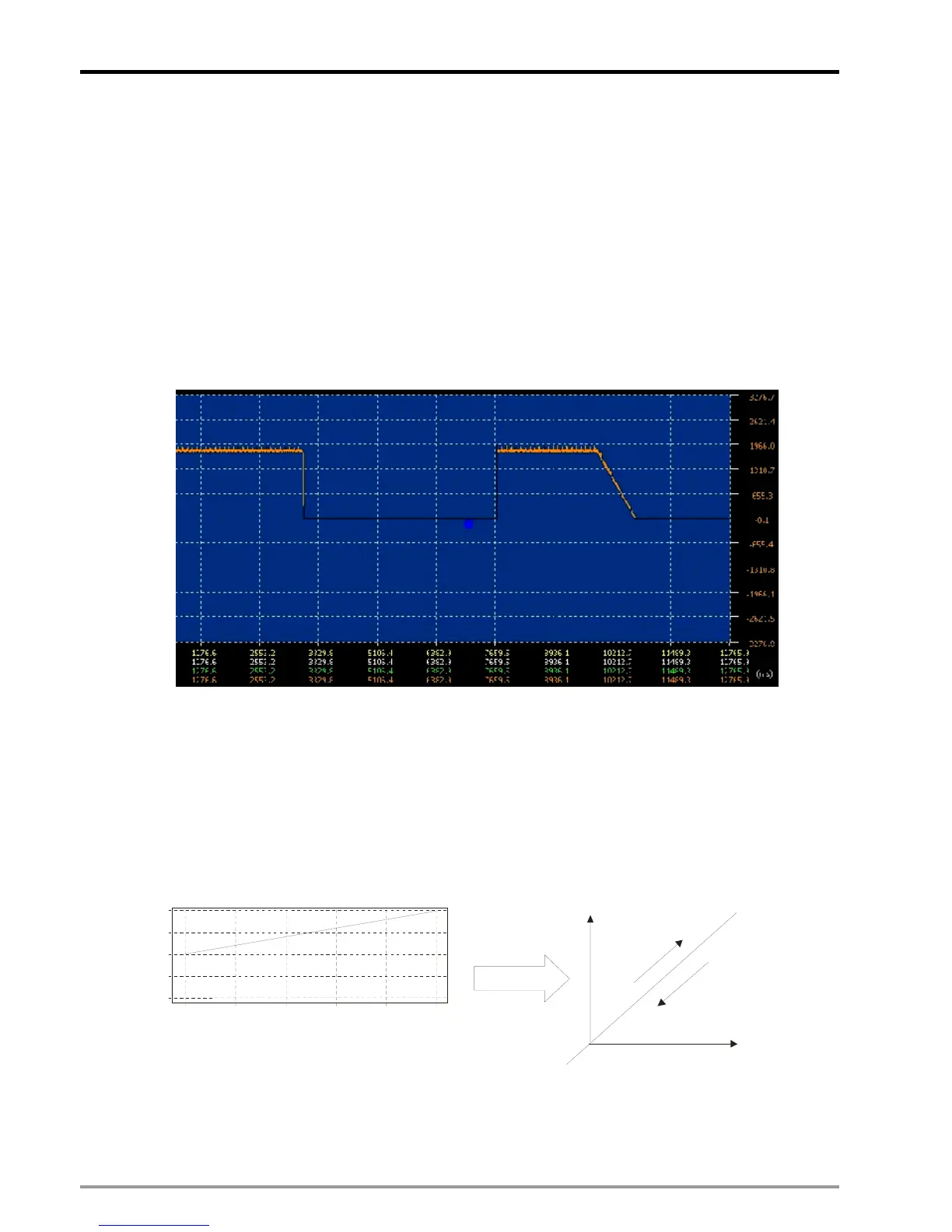
In addition, for point-to-point switching pattern, if E-CAM max frequency (DD1840) is set as 0Hz and the
value of deceleration time T
DEC
(D1837) is specified, E-CAM will decelerate to stop. The below diagram
indicates the diference between normal stop operation and stop operation with deceleration.
2. Forward / reverse Running Pattern
To enable forward / reverse running pattern, bit 12, 11 of D1847/D1927/D1927 (work mode setting) should
be set ON (K3). In forward / reverse running pattern of multi-axis E-CAM, the execution of Slave will be in
the same direction as Master. In reverse running operation, the execution will start again from the end of the
data when Master position 0 is reached. Therefore, please note that forward/reverse running pattern can not
be used with point-to-point switching pattern otherwise error will occur. The below diagrams illustrate the
execution of 2 E-CAM Charts.
10,000
5,000
0
-5,000
-10,000
2,000
4,000 6,000
8,000
0
10,000
Slav
 Loading...


