9 Electrical CAM
DVP-PM Application Manual
9-9
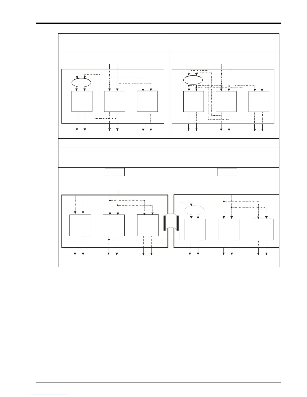
The source signal of X axis is from FP1, RP1 (Y
axis as virtual Master), and the source signal of Y,
Z axis is from A1, B1 input of MPG1.
The source signal of X, Z axis is from FP1, RP1
(Y axis as virtual Master), and the source signal of
Y axis is from A1, B1 input of MPG1.
C200
A B
FP RP
FP0 RP0
FP1 RP1
FP2 RP2
A B
A B
X ax is
Y axis Z axis
A1 B1
FP RP FP RP
20PM
MPG1
C200
A B
FP RP
FP0 RP0
FP1 RP
FP2 RP2
A B
A B
X axis
Y axis
Z ax is
A1 B1
FP RP FP RP
20PM
MPG1
M1909 = OFF, M1910 = ON
Take FP signals of previous MPU (Master) as the source signal for Slave through communication.
When M1910 = ON, FP1 of MasterPLC will sent out signals to C200 of Slave PLC as the source
signals of virtual master.
C200
A B
FP RP
FP0 RP
FP1 RP1
FP2 RP2
A B
A B
X axis
Y axis
Z ax is
A1 B1
FP RP FP RP
20PM
MPG1
20PM
A B
FP RP
FP0 RP
FP1 RP1
FP2 RP2
A B
A B
X ax is
Y axis
Z ax is
FP RP FP RP
A1 B1
MPG1
A0 B0
MPG0
Master
Slave
Note: According to our measurement, delay time for connecting single DVP-PM is 0.07us. Connection
with up to approximately 29 MPUs will delay only 2us, equaling to a 500kHz pulse. Therefore, signal
attenuation for this application is insignificant.
9.2.3 Start / Stop E-CAM
9.2.3.1 Start / Stop Cyclic E-CAM
In cyclic E-CAM, Master and Slave operate according to the user-defined E-CAM Data and repeat the E-CAM
Data constantly.
E-CAM Data

 Loading...


