9 Electrical CAM
DVP-PM Application Manual
9-10
Slave
max
=180()Slave unit
Master =360
max
()
Master unit
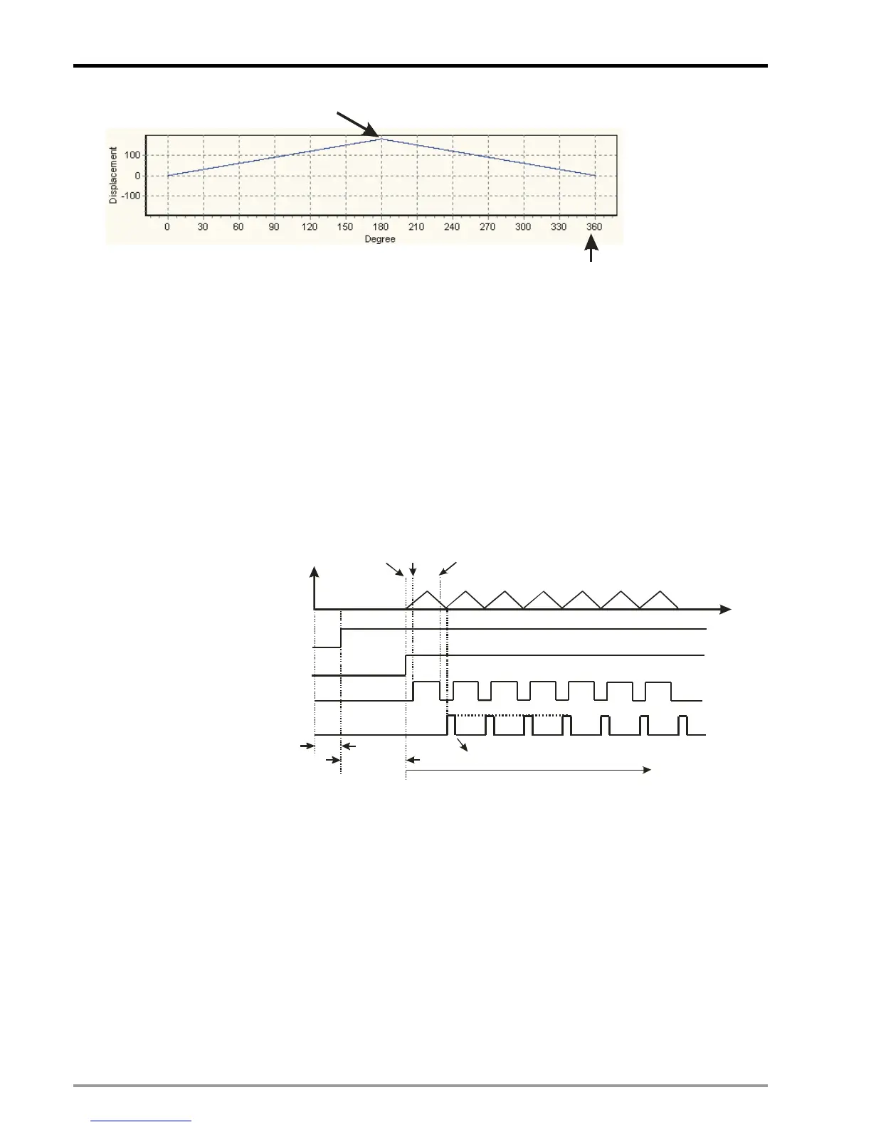
Start Cyclic E-CAM
The timing diagram below indicates an operation process of cyclic E-CAM operation with synchronized
output position between 60~300.
1. In T1, D1846 bit 13 = ON, cyclic E-CAM is enabled.
2. After the initialization interval of T2, M1812 = ON to indicate the completion of E-CAM initialization.
3. In T3, cyclic operation starts after M1812 = ON. Slave executes with Master constantly according to the
E-CAM Data.
4. At the same time, CLR0 outputs according to the synchronized output range. When M1813 = ON, an
E-CAM cycle is completed. User has to reset the flag for indicating the completion of other E-CAM
cycles.
D1846 b13=ON
enables cyclic E-CAM
M1812=ON,
initialization completed
CLR0 sync output
M1813, E-CAM completion
T1
T2
T
n
n+60 n+300
Slave
Position
Master
position
Reset by user
Stop Cyclic E-CAM
There are two ways to stop cyclic E-CAM:
1. When D1846 bit 13 (enabling cyclic E-CAM) = OFF, Slave of E-CAM stops immediately.

 Loading...


