3 Functions of Devices in DVP-PM
DVP-PM Application Manual
3-6
Binary
(BIN)
Octal
(OCT)
Decimal
(DEC)
Binary Code Decimal
(BCD)
Hexadecimal
(HEX)
For DVP-PM internal operation
No. of device X,
Y
Constant K and No.
of device M, S, T, C,
D, V, Z, P
For DIP switch and 7-segment
display
Constant H
0000 1100 14 12 0001 0010 C
0 0 0 0 1 1 0 1 15 13 0 0 0 1 0 0 1 1 D
0 0 0 0 1 1 1 0 16 14 0 0 0 1 0 1 0 0 E
0000 1111 17 15 0 0 0 1 0 1 0 1 F
0 0 0 1 0 0 0 0 20 16 0 0 0 1 0 1 1 0 10
0001 0001 21 17 0 0 0 1 0 1 11 11
: : : : :
0 1 1 0 0 0 1 1 143 99 1 0 0 1 1 0 0 1 63
3.3 Numbering and Function of External Input/Output Contacts [X] / [Y]
Input relay X0 ~ X377
The numbering of input relay (or input terminal) is in octal format. DVP-PM is designed for up to 256 points, and
the range is: X0 ~ X7, X10 ~ X17, ...X370 ~ X377.
Output relay Y0 ~ Y377
The numbering of output relay (or output terminal) is in octal format. DVP-PM is designed for up to 256 points,
and the range is: Y0 ~ Y7, Y10 ~ Y17, …Y370 ~ Y377.
Function of input contact X
The input contact X is connected to input devices and reads the input signals into DVP-PM. There is no limitation
on the times of using NO (Normally Open) / NC (Normally Closed) contacts in the program. ON/OFF of the input
contact X only changes with ON/OFF status of the connected devices. PMSoft can not force ON/OFF the input
contact X.
M1304, Force ON/OFF contact X
When M1304 = OFF, input contact can not be force ON/OFF by PMSoft; when M1304 = ON, input contact X can
be force ON/OFF by PMSoft. However, the function of updating input signals will be disabled in this case.
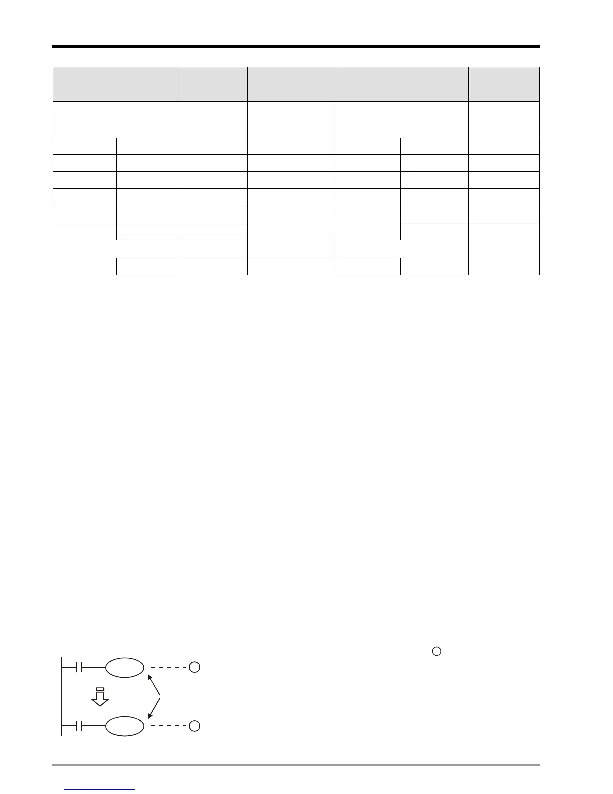
Function of output contact Y
Output contact Y sends out ON/OFF signals to drive the load connected to output contacts. There are two types
of output contacts, relay and transistor. There is no limitation on the times of using Y contacts (NO / NC) in the
program. However, we suggest users do not repeat the No. of output coil Y; otherwise, according to the scan
principle of ladder diagram, the status of output coil will be determined by the status of the last Y in the program.
X0
X10
Y0
Y0
1
2
Y0 is repeated.
The output of Y0 will be determined by Y0 in
2
, i.e. ON/OFF of X10
will determine the output status of Y0.

 Loading...


