9 Electrical CAM
DVP-PM Application Manual
9-33
Parameteres Data Format Explanations
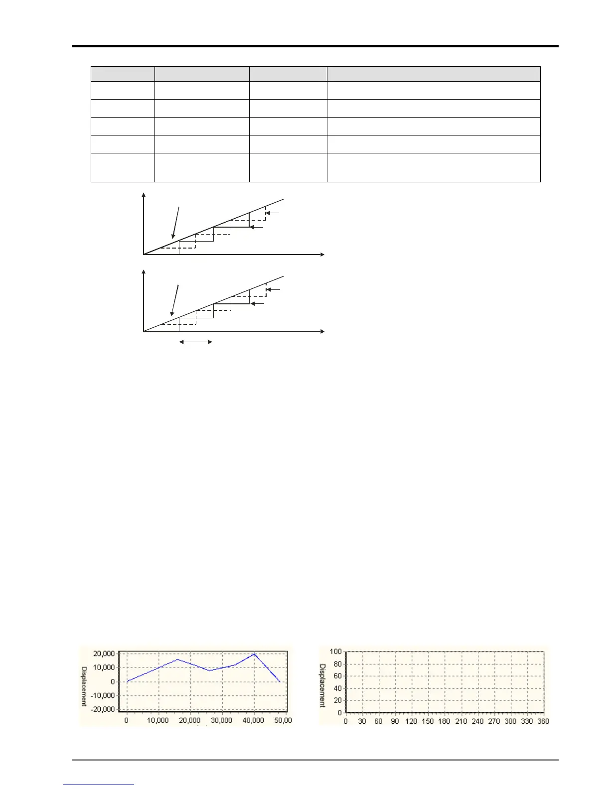
P1 Slave position 1 Integer Caught at DOG signal
P2 Slave position 2 Integer Caught at end of cycle
P3 Master position 1 Integer Caught at DOG signal
P4 Master position 2 Floating point Caught at end of cycle
P5
Master position 3
Floating point
Caught at START0(M1746=OFF) or
PG0(M1746=ON)
D1849, D1848
D101, D100
D103, D102
T(ms)
Slave position caught at DOG signal
Current position of X-axi
D105, D104
D107, D106
D1863, D1862
Number of accumulated MPG pulses
E-CAM cycle
Slave position caught at end of cycle
Master position caught at DOG signal
Master position caught at end of cycle
The function of reading E-CAM status in capture mode should be used with M1757 (Remain current speed), and
can be applied for checking the cutter position in flying saw applications. For details please refer to 9.4.2.6.
9.4.2.1 E-CAM Data Real-time Modification
E-CAM Data set in E-CAM Chart will be downloaded into DVP-PM with the user program. Due to that
E-CAM Data can only be modified by PMSoft, users have to download E-CAM Data again after modification.
Aiming at this problem DVP-PM also provides users with E-CAM Data real-time Modification function by
DTO/DFROM instruction
Data length of E-CAM Data can be real-time modified. When 4 words of one point (set) of E-CAM Data are
all 0 and identified, DVP-PM will take it as E-CAM completion. Therefore, if you want to modify 10 points
E-CAM Data into 5 points, DTO instruction can be applied to write 0 into the 4 words of the 6
th
point.
Application Example
Modify the original E-CAM Data (existed data or no data) as diagram (a) into the 3-point E-CAM Data as
Diagram (b) with coordinate (0, 0), (16000, 10000) and (32000, 0).
or

 Loading...


