9 Electrical CAM
DVP-PM Application Manual
9-63
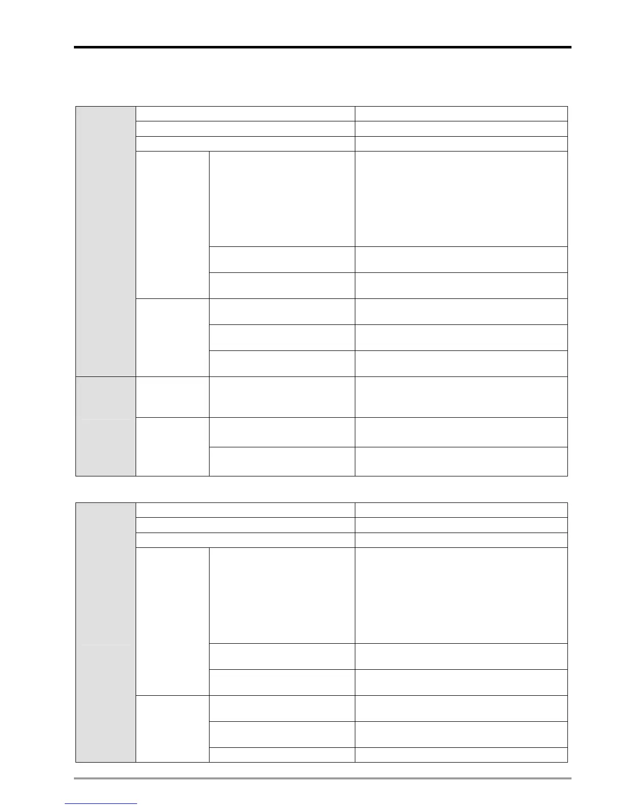
Here are 2 examples of obtainng the settings of Master and Slave
Example 1
Rounds per layer N1 = 10
Total rounds of winding N2 = 80
Coil spacing (mm) D = 0.2
Mechanism parameter
(mm/revolution)
There is no actual moving distance of Master
because winding shaft is directly driven by
signals. The winding principle is that Slave
moves certain distance when Master rotates a
round, therefore mechanism parameter of
Master can be regarded the same as that of
Slave.
A
Master
= A
Slave
Servo parameter
(pulses/revolution)
B
Master
= 3600
Winding shaft
(Master/Y
axis)
Mechanical parameter
(mm/pulses)
C
Master
= A
Master
/B
Master
Mechanism parameter
(mm/revolution)
A
Slave
= 10
Servo parameter
(pulses/revolution)
B
Slave
= 10000
Input
parameters
Coil shaft
(Slave/X axis)
Mechanical parameter
(mm/pulses)
C
Slave
= A
Slave
/B
Slave
Winding shaft
(Master/Y
axis)
Length of single speed
positioning (pulses)
=N2 x B
Master=
= 80 x 3600 = 288000
Master
Max
(pulses)
=2 x N1 x B
Master
= 2 x 10 x 3600 = 72000
“2” indicates double layer winding
Settings
Coil shaft
(Slave/X axis)
Slave
max
(pulses)
=N1 x D/C
Slave
= 10 x 0.2 / (0.1/100)
=2000
Example 2
Rounds per layer N1 = 20
Total rounds of winding N2 = 100
Coil spacing (mm) D = 0.3
Mechanism parameter
(mm/revolution)
There is no actual moving distance of Master
because winding shaft is directly driven by
signals. The winding principle is that Slave
moves certain distance when Master rotates a
round, therefore mechanism parameter of
Master can be regarded the same as that of
Slave.
A
Master
= A
Slave
Servo parameter
(pulses/revolution)
B
Master
= 3600
Winding shaft
(Master/Y
axis)
Mechanical parameter
(mm/pulses)
C
Master
= A
Master
/B
Master
Mechanism parameter
(mm/revolution)
A
Slave
= 10
Servo parameter
(pulses/revolution)
B
Slave
= 10000
Input
parameters
Coil shaft
(Slave/X axis)
Mechanical parameter
C
Slave
= A
Slave
/B
Slave

 Loading...


