12 POU Editing Mode
DVP-PM Application Manual
12-42
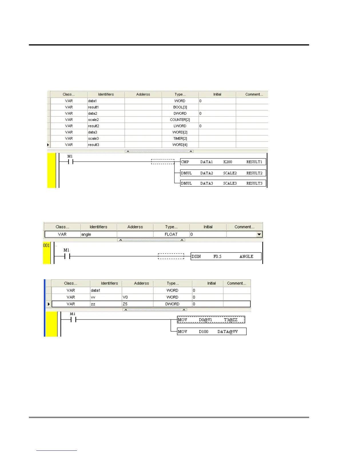
RESULT2. DATA2. In this case, only 32-bit data type including DWORD, WORD[2], TIMER[2], COUNTER[2] can
be specified for “data2” as below. This rule applies to other symbols and instructions. With correct combinations
between symbols and instructions, PMSoft can allocate proper devices when compiling.
For floating point instructions, the operand D should be specified with a symbol declaring data type as FLOAT.
Take the below diagram for example, The symbol “angle” in floating point instruction DSIN should be specified as
FLOAT in Type column.
Character “@” should be added when using indexes V or Z as below.
Users can add index number in brackets “[]” after data type to apply designated data in the data string. For
example, the last operand (STATE) of CMP instruction occupies 3 bits, so “state” in the symbol table should be
declared as BOOL[3], creating 3 conditions including STATE[0], STATE[1] and STATE[3] for processing different
operation results of CMP instruction.

 Loading...


