13 CANopen Communication Card
DVP-PM Application Manual
13-12
CRn11~CRn12: Manufacturer’s error code
[Explanations]
Display the error code defined by the manufacturer when error occurs on certain servo drive. For error code
details please refer to the manual of Delta ASDA-A2 servo drive.
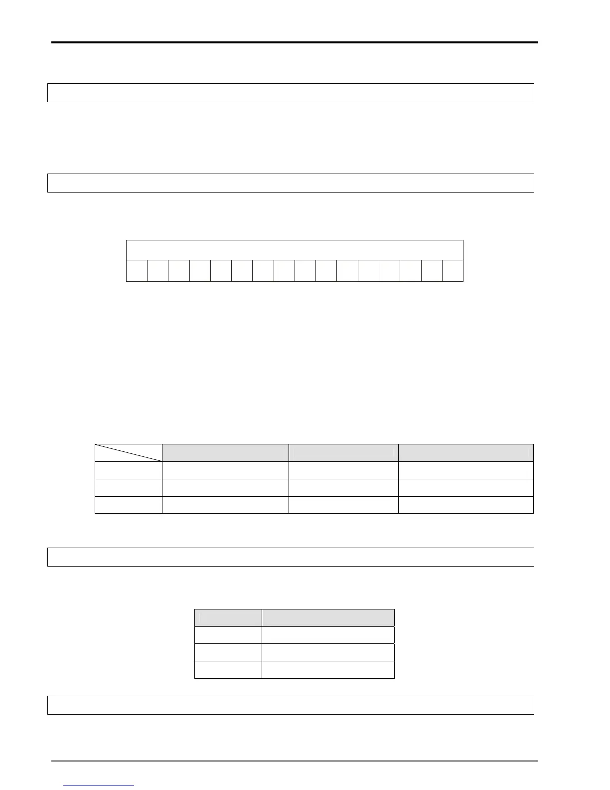
CRn20: Servo drive status
[Explanations]
Display the current status of ASDA-A2. For the status codes, please refer to the table below.
RS
XSO
FT
012345678910111
QS
WR
X
X
TR
OM
OM
X
X
Status word
Bit
X
RM
OM
RS: Servo ready. When servo initialization is completed, the bit will be 1, indicating the ready status.
SO: Sevo On. The bit will be 1 when the servo drive is ON.
FT: Error flag. When error occurs in the servo drive, the flag will be 1.
QS: Quick stop. The user can execute quick stop on the servo when the bit is 1.
WR: Warning. When the servo sents warning messages, the bit will be 1.
RM: Remote monitor. Remote monitor is applicable when the bit is 1.
TR: Motion command completed. When motion command is completed, the bit will be 1.
OM[14~12]: Indicates status of each operating mode. Please see the table below.
Profile position mode Homing mode Interpolation position mode
OM[12] Position setting completed Executing Homing Executing interpolation
OM[13] Following error Homing error X
OM[14] X X SYNC executes
Note: “X” indicates “Reserved”
CRn21: Current operating mode of servo drive
[Explanations]
Display the current operating mode of the servo.
Content Operating mode
0x01 Profile position mode
0x06 Homing mode
0x07 Interpolation position mode
CRn22~CRn23: Servo drive position
[Explanations]
Display the current position of servo drive in DWORD format.

 Loading...


