3 Functions of Devices in DVP-PM
DVP-PM Application Manual
3-45
3. The relative registers are listed as below.
X - axis Y- axis Z - axis Function
M1761 M1841 M2001 Stop at fixed position
D1839, 1838 D1919..1918 D1999..1998 Stop position
D1843, 1842 D1923..1922 D2003, 2002 Pulses per round
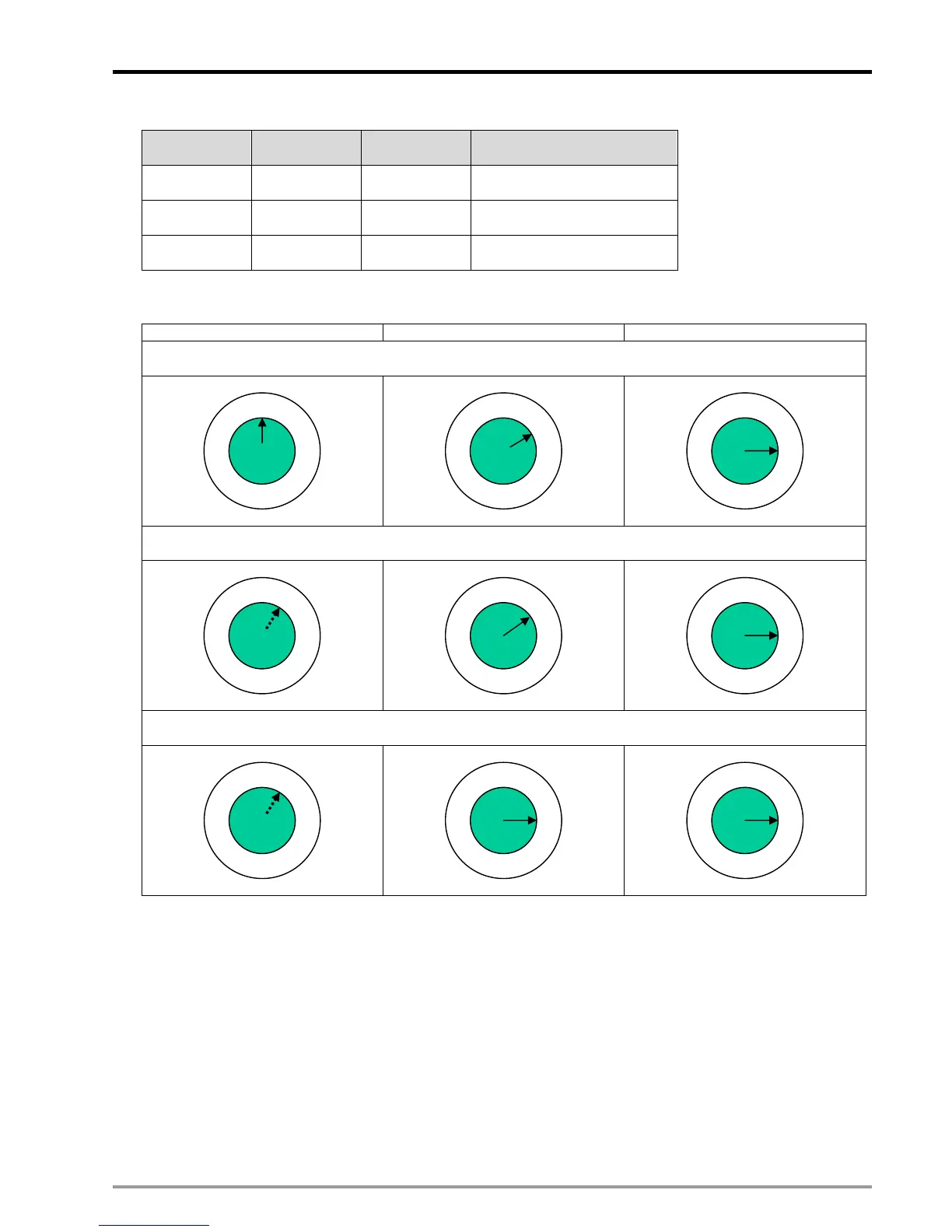
4. For example, if pulses per round is set as 20,000 and the target stop angle is 90 degree, the setting of stop
position could be the cases below:
Start position JOG+ to stop Stop position
Case 1: If the operation starts at 0 degree and JOG+ signal is triggered at position 4000, it should stop at
position 5000
0 degree
Position: 4000
Position: 5000 (90 degree)
Case 2: If the operation starts at random degree and JOG+ signal is triggered at position 63500, it should stop
at position 65000.
Random degree
Position: 63500
Position: 65000 (90 degree)
Case 3: If the operation starts at ramdom degree and JOG+ signal is triggered at position 25001, it should go
19999 pulses and stop at position 45000.
Random degree
Position: 25001
Position: 45000 (90 degree)
Function Group:
Error Status of Motion Control
Number:
M1793, D1857, M1873, D1937, M2033, D2017
Explanations:
1. When errors occur on X, Y or Z axis, the corresponding error flags M1793, M1873 and M2033 will be ON, and the
error messages will be stored in D1857, D1937 and D2017.
2. To eliminate the error, please clear the error message registers and reset the error flags.
 Loading...


