A-18
EMVJ-PG01U
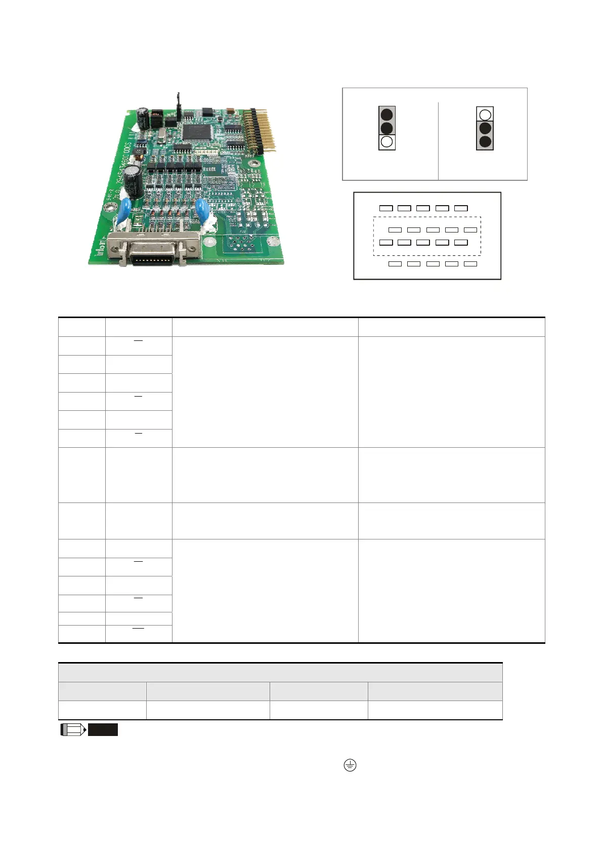
FSW2
Standard UVW
Output Encoder
Delta Encoder
11
2
1
12
10
9
8
20
19
Layout of J1 Drive Connector
Functions of Terminals
Pin No Terminal Mark Function, Description Specifications
4
A
5
A
7
B
9
B
10
Z
2
Z
Differential incremental signal input of
the encoder
Line Driver (Line Driver RS422)
Maximum Input Frequency 300kHz
14, 16
VP
Encoder power output
Note: FSW3 can be used to configure the
output as +5V or +12V.
Voltage: +5V±0.5V or +12V±1V
Current: 200mA max
13, 15
0V
Power common dedicated for the
encoder
Reference level for the encoder power
19
U
8
U
6
V
1
V
11
W
3
W
Differential absolute signal input of the
encoder (UVW 3-bit encoding)
Line Driver (Line Driver RS422)
Maximum Input Frequency 50kHz
Wiring Length
Encoder Wiring - Diameter mm² (AWG)
Core Size Number of Cores Wire Standard Standard Wire Length
0.13(AWG26)
10 (4 pairs) UL2464 3 m (9.84 feet)
NOTE
1) For wiring the encoder, please use the shielded twisted-pair cable so as to reduce the interference due to noise.
2) The shield net must be firmly connected with the SHIELD terminal
.
3) During wiring, please follow the corresponding provisions for cable wiring so as to avoid hazards and accidents.
 Loading...