4. Description of Parameters
4-15
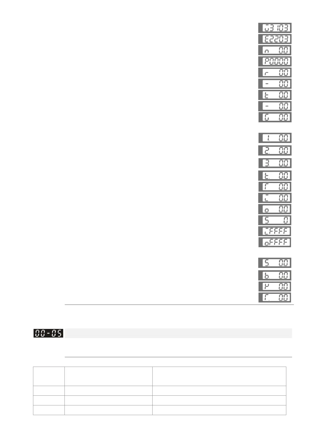
3: Display the DC-BUS voltage (U)
U
4: Display the output voltage (E)
U
5: Display the output power angle (n)
U
6: Display the output power in kW (P)
U
7: Display the actual motor speed(r 00: forward speed; - 00:
negative speed)
U
U
8: Display the estimated output torque (%) (t 0.0: positive
torque; - 0.0: negative torque) (%)
U
U
9: Display the PG feedback (G)
U
10: Reserved
11: Display the signal value of the analog input terminal PO
with 0~10V mapped to 0~100%
U
12: Display the signal value of the analog input terminal PI
with 0~10V mapped to 0~100%
U
13: Display the signal value of the analog input terminal PI
with -10~10V mapped to 0~100%
U
14: Display temperature of the heat sink in °C (t.)
U
15: Display temperature of the IGBT power module °C
U
16: The status of digital input (ON/OFF)
U
17: The status of digital output (ON/OFF)
U
18: Reserved
U
19: The corresponding CPU pin status of the digital input
U
20: The corresponding CPU pin status of the digital output
U
21~24: Reserved
25: Display the signal value of the analog input terminal OI
with 0~10V mapped to 0~100%
U
26: Display the actual pressure value (Bar)
U
27: Display the kWh value
U
28: Display the motor temperature (currently only support
KTY84)
U
This parameter defines the contents to be displayed in the U page of the digital keypad
KPV-CE01 (as shown in the figure).
a
Analog output function selection
Control mode VF FOCPG FOCPM
Factory default: 0
Settings 0~20
Summary of functions
Setting
Value
Function Description
0 Output frequency (Hz) The maximum frequency is 100%
1 Frequency command (Hz) The maximum frequency is 100%
2 Motor speed (Hz) 600Hz is used as 100%
 Loading...