EXT. IN
DC 12V 20mA MAX.
EXT. IN-2 PRE OUT
V. AUX VCR-1 VCR-2 VCR-3 VCR-1 VCR-2 VCR-3
SURR.
SURR.
SURR.
EXT. IN-1
EXT. IN
DC 12V 20mA MAX.
EXT. IN-2 PRE OUT OUT
V. AUX VCR-1 VCR-2 VCR-3 VCR-1 VCR-2 VCR-3
SURR.
SURR.
SURR.
SWITCHED 100W MAX.
Another room
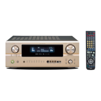
Integrated pre-main amplifier
Extension jacks for future use.
For instructions on operations using the MULTI ZONE jacks, see pages 22, 23.
Connecting the MULTI ZONE jacks
• If another pre-main (integrated) amplifier is connected, the multi-zone jacks can be used to play a different
program source in another room at the same time. (See pages 22, 23.)
Speaker Impedance
• Speakers with an impedance of from 6 to 16
Ω/ohms can be connected for use as front and
center speakers.
• Speakers with an impedance of 6 to 16 Ω/ohms can
be connected for use as surround speakers.
• The protector circuit may be activated if the set is
played for long periods of time at high volumes
when speakers with an impedance lower than the
specified impedance are connected.
NOTE:
NEVER touch the speaker terminals when the power is on.
Doing so could result in electric shocks.
Connecting the speaker cords
1. Loosen by turning
counterclockwise.
2. Insert the cord. 3. Tighten by turning
clockwise.
Either tightly twist or terminate the core wires.
Protector circuit
• This unit is equipped with a high-speed protection circuit. The purpose of this circuit is to protect the
speakers under circumstances such as when the output of the power amplifier is inadvertently short-
circuited and a large current flows, when the temperature surrounding the unit becomes unusually high,
or when the unit is used at high output over a long period which results in an extreme temperature rise.
When the protection circuit is activated, the speaker output is cut off and the power supply indicator LED
flashes. Should this occur, please follow these steps: be sure to switch off the power of this unit, check
whether there are any faults with the wiring of the speaker cables or input cables, and wait for the unit
to cool down if it is very hot. Improve the ventilation condition around the unit and switch the power back
on.
If the protection circuit is activated again even though there are no problems with the wiring or the
ventilation around the unit, switch off the power and contact a DENON service center.
Note on speaker impedance
• The protector circuit may be activated if the set is played for long periods of time at high volumes when
speakers with an impedance lower than the specified impedance (for example speakers with an
impedance of lower than 4 Ω/ohms) are connected. If the protector circuit is activated, the speaker output
is cut off. Turn off the set’s power, wait for the set to cool down, improve the ventilation around the set,
then turn the power back on.
Cooling fan
• The AVC-A1SR is equipped with a cooling fan to prevent the temperature inside the set from rising. The
fan is activated under certain usage conditions. It is temperature and volume level sensitive, to minimize
or prevent audible fan noise.
Speaker system connections
• Connect the speaker terminals with the speakers
making sure that like polarities are matched ( < with
< , > with > ). Mismatching of polarities will result
in weak central sound, unclear orientation of the
various instruments, and the sense of direction of
the stereo being impaired.
• When making connections, take care that none of
the individual conductors of the speaker cord come
in contact with adjacent terminals, with other
speaker cord conductors, or with the rear panel.
TRIGGER OUT
DC 12V turns on and off when the product’s power is turned on and off.
CONTROL terminal
Perform the following operation before using an external controller connected to the RS-232C terminal:
1. Press the ON/STANDBY button on the main unit and set the unit to the operating mode.
2. Perform the operation to turn off the power from the external control.
3. Check that the product has been set to the standby mode.
After checking the above, check the connections of the external controller. Operation is possible.
 Loading...