q
Transmitter
w
Touch panel
e
CHANNEL up/down buttons
r
MUTE button
t
USB terminal
y
Jog stick (PUSH ENTER)
u
VOL. (volume) up/down buttons
i
LIGHT (back light) button
o
Reset button
!0
Battery cover
Remote control unit
• For details, refer to the separate (supplied) RC-871 operating instructions.
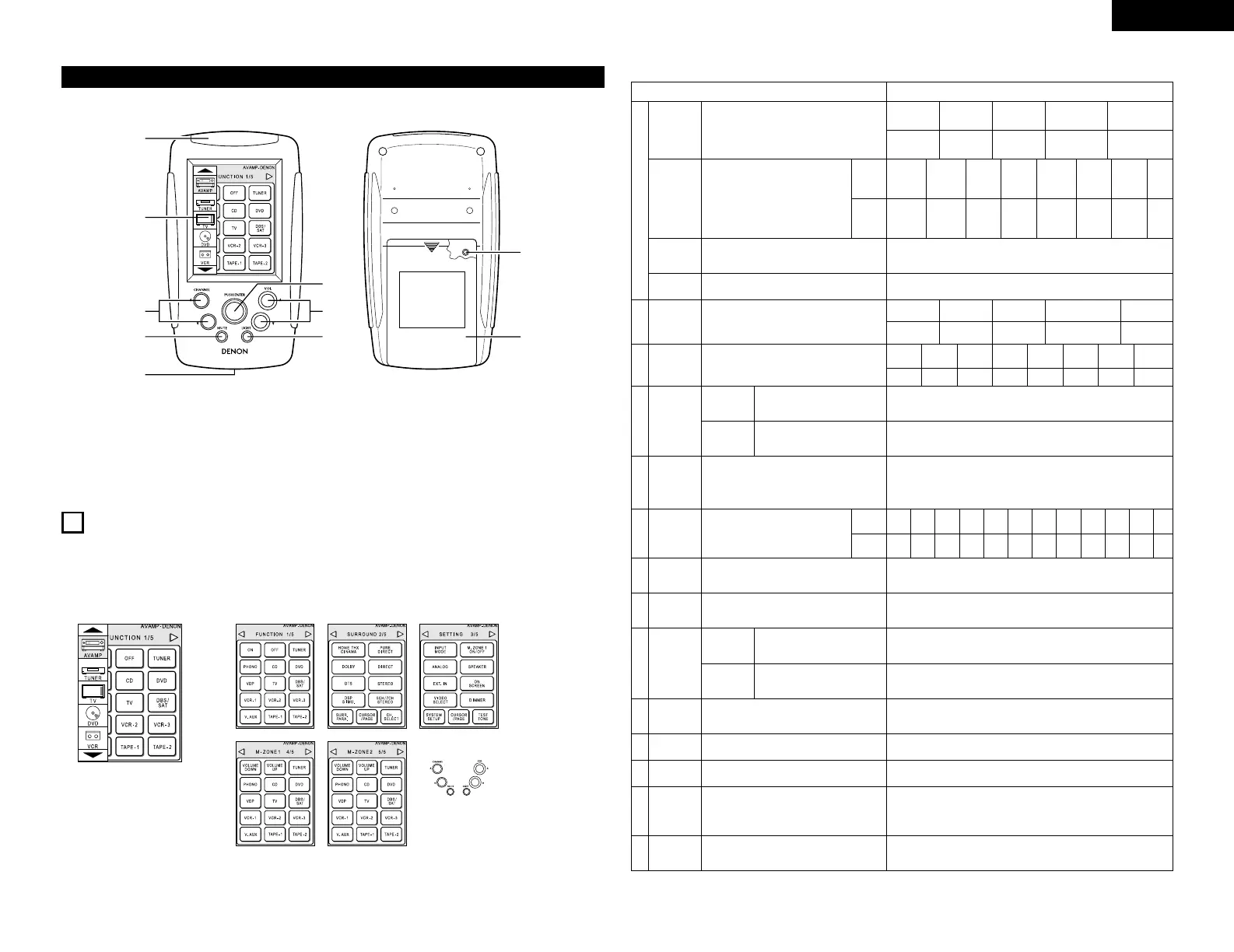
• System setup items and default values (set upon shipment from the factory)
Screen while icons are displayed
Transmission codes
of independent buttons
CHANNEL• : Tuner preset
CHANNELª : Tuner preset
VOL• : Main volume of AV amplifier
VOLª : Main volume of AV amplifier
MUTE : Muting of AV amplifier
7
SETTING UP THE SYSTEM
• Once all connections with other AV components have been completed as described in “CONNECTIONS”
(see pages 4 to 8), make the various settings described below on the monitor screen using the AVC-A1SR’s
on-screen display function.
These settings are required to set up the listening room’s AV system centered around the AVC-A1SR.
• Use the following buttons to set up the system:
System setup Default settings
q
!4
e
t
y
!3
Speaker
Configuration
(Surround
Speaker
Setting)
Crossover
Frequency
Setup Lock
Channel
Level
Subwoofer
Peak Limit
Lev
Digital In
Assignment
On Screen
Display
Input the combination of speakers in your
system and their corresponding sizes (Small for
regular speakers, Large for full-size, full-range) to
automatically set the composition of the signals
output from the speakers and the frequency
response.
Use this function when using multiple
surround speaker combinations for more
ideal surround sound. Once the
combinations of surround speakers to
be used for the different surround
modes are preset, the surround
speakers are selected automatically
according to the surround mode.
Set the frequency (Hz) below which the bass sound
of the various speakers is to be output from the
subwoofer.
Set whether or not to lock the system setup
settings so that they cannot be changed.
This adjusts the volume of the signals output from
the speakers and subwoofer for the different
channels in order to obtain optimum effects.
This parameter is for detecting the maximum level
of the low bass signals output from the subwoofer
channel in order to protect the subwoofer from
damage and prevent unpleasant distorted sounds
from being produced.
This assigns the digital input jacks for the
different input sources.
This sets whether or not to display the on-screen
display that appears on the monitor screen when
the controls on the remote control unit or main unit
are operated (from MONITOR 1 outputs only).
Surround
mode
Surround
speaker
Input
source
Digital
Inputs
Front Sp.
Small
Center Sp. Surround Sp.Sub Woofer
Small SmallYes
DOLBY/
DTS
SURROUND
THX
THX 5.1
WIDE
SCREEN
5CH/7CH
STEREO
DSP
SIMULATION
MULTI
CH
DIRECT
——
A AAAAA——
FIXED —THX—
Front L & R Center Surround L & RSub Woofer
3.60 m (12.0 ft) 3.60 m (12.0 ft) 3.00 m (10.0 ft)3.60 m (12.0 ft)
Front L
Front R Center
Surround
R
Surround
Back R
Subwoofer
0.0 dB 0.0 dB 0.0 dB 0.0 dB 0.0 dB 0.0 dB
Peak Limiter = OFF
CD
COAXIAL
1
On Screen Display = ON
Surround
Back Sp.
Small / 2spkrs
Setup Lock = OFF
w
Delay Time
This parameter is for optimizing the timing with
which the audio signals are produced from the
speakers and subwoofer according to the listening
position.
SBL & SBR
3.00 m (10.0 ft)
o
Multi Zone
Control
This sets the output level for the
multi-zone1 output jacks.
Variable
Surround
Back L
0.0 dB
Surround
L
0.0 dB
Multi Zone1
vol. Level
Power AMP
Assignment
Set this to switch the surround
back channel’s power amplifier for
use for multi-zone2.
Surround Back
Subwoofer
mode
This selects the subwoofer speaker for playing
deep bass signals.
LFE —THX—
r
THX Audio
Setup
When using a THX Ultra2
compatible subwoofer, set the
subwoofer’s frequency response.
THX Ultra2 Subwoofer = NO
Boundary
Gain
compensation
Surround
Back
Speaker
Position
When using two surround back
speakers, set the distance of the
two speakers.
The Distance Between SBL/SBR = 0 m to 0.3 m
(
0 ft to 1 ft
)
u
Video Input
Mode
Set the input signal to be output from the monitor
output terminal.
AUTO
i
Audio Delay
Adjust the time delay of the video and audio
signals.
Audio Delay = 0 ms
!0
Auto
Surround
Mode
Auto surround mode function setting. Auto Surround Mode = ON
!1
Ext. In
Setup
Set the Ext.In terminal playback method. MODE = DSP, S.Back = NOT USED, SW Level = 15 dB, INPUT Vol. = 0 dB
!2
Digital Multi
Ch In
Digital multichannel input setting. DENON Link = OFF, Digital Ext. In = OFF
DVD VDP TV
DBS/
SAT
VCR-1 VCR-2
TAPE-1
COAXIAL
2
COAXIAL
3
OPTICAL
1
OPTICAL
2
OPTICAL
3
OPTICAL
4
OPTICAL
5
V. AUX
COAXIAL
5
VCR-3
COAXIAL
4
TAPE-2
OPTICAL
6
TUNER
OFF
 Loading...