ENGLISH
o
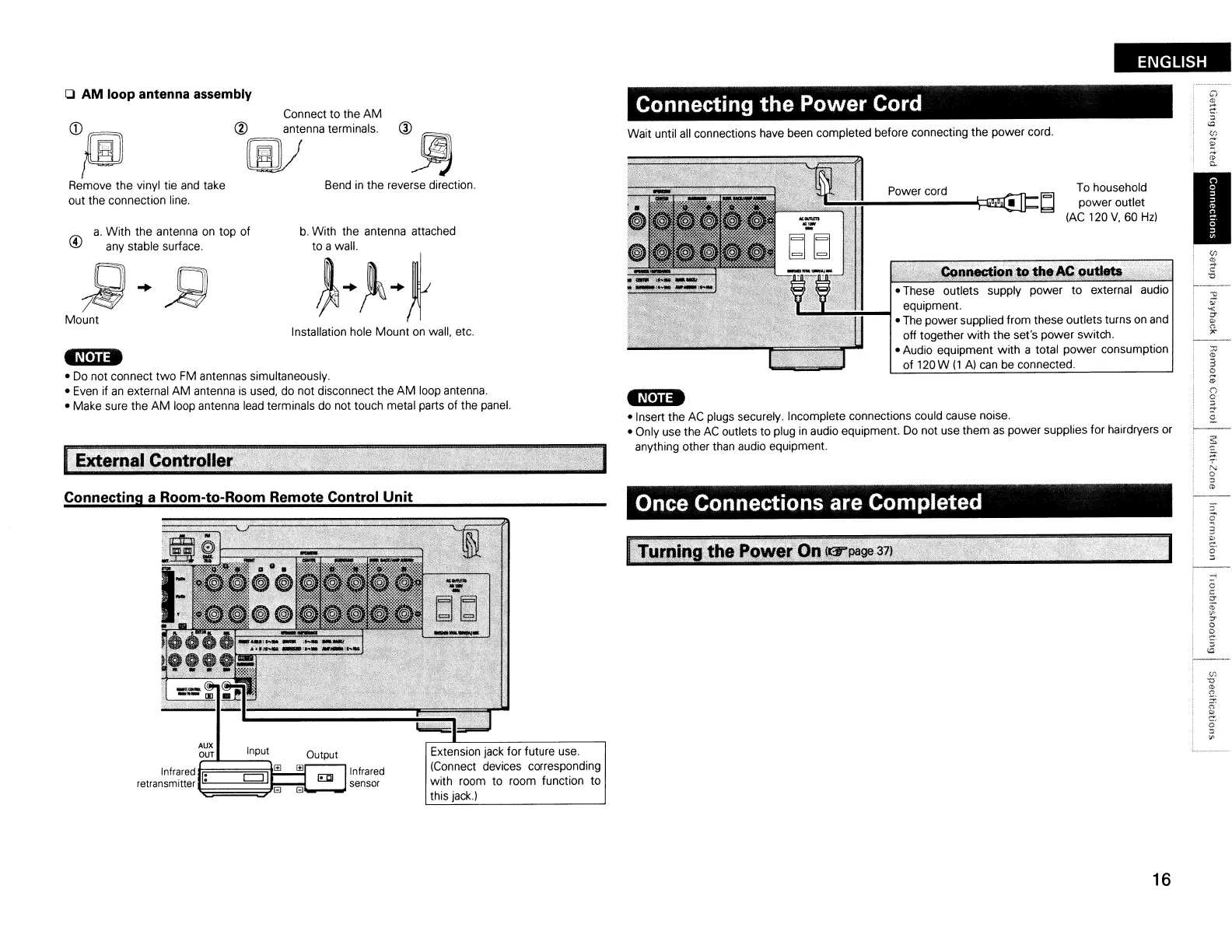
AM
loop antenna assembly
I
,.tl;~;.;¥d,;~n~A·~
th.AC:pu~.;r
",,,;X
• These outlets supply power
to
external audio
equipment.
• The power supplied from these outlets turns
on
and
off together
with
the set's power switch.
• Audio equipment
with
a total power consumption
of
120W
(1
A)
can
be connected.
Power cord
To
household
~~!-"';''':':''':':''':':;';';;'-~:::1ii!j5l'i.III=
bJ
power outlet
lAC 120
V,
60
Hz)
Connecting
the
Power Cord
Wait until all connections have been completed before connecting the power cord.
t~[·n·
• Insert the
AC
plugs securely. Incomplete connections could cause noise.
• Only use the
AC
outlets to plug
in
audio equipment.
Do
not use them
as
power supplies for hairdryers or
anything other than audio equipment.
b.
With the antenna attached
J:~+t
Installation hole Mount
on
wall, etc.
Bend
in
the reverse direction.
Connect to the
AM
@ antenna terminals. ®
~
[jJ)
~
ri\
a.
With the antenna
on
top of
\!I
any stable surface.
®}[ID
Remove the vinyl tie and take
out the connection line.
~+j;)
Mount
tN.n.
• Do not connect
two
FM antennas simultaneously.
• Even if
an
external AM antenna
is
used, do not disconnect the
AM
loop antenna.
• Make sure the
AM
loop antenna
lead
terminals do not touch metal parts of the panel.
Once Connections are Completed
Extension jack for future use.
(Connect devices corresponding
with room to room function to
this
jack.)
Infrared
sensor
r;;~=;ln~p;ut~I>l!.....!I>l~Output
Infrared
~.
c::::J
I
EllJ
retransmitler
~·~~~~thEl,BlEI
Connecting a Room-to-Room Remote Control
Unit
16
 Loading...