l
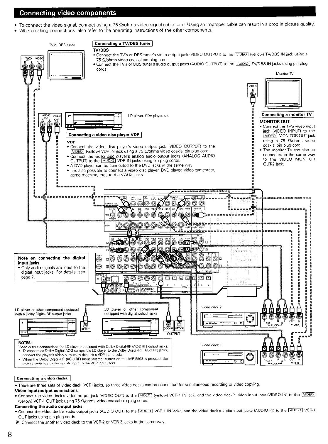
To connect the video signal, connect using a 75 Q/ohms video signal cable cord. Using an improper cable can result in a drop in picture quality.
l
When making connections, also refer to the operating instructions of the other components.
1 Connecting a TV/DBS tuner 1
TVIDBS
l
Connect the TV’s or DBS tuner’s video output jack (VIDEO OUTPUT) to the m (yellow) TV/DES IN jack using a
75 Q/ohms vtdeo coaxial pan plug cord.
. Connect the TV’s or DBS tuner’s audio output jacks (AUDIO OUTPUT) to the m N/DBS IN jacks using pin plug
cords.
Monitor ni
--
:
R
1 Connecting a monitor TV )
: MONITOR OUT
:
l
Connect the TV’s
video input
:
jack (VIDEO INPUT) to the
:
jVlDEOi MONITOR OUTjack
using a 75 n/ohms video
:
coaxtal ptn plug cord.
:
l
The tmonttor TV can also be
:
connected in the same way
to the VIDEO MONITOR
:
OUT-Z jack.
P
1 Connecting a video disc player VDP 1
I
:
VDP
I:
l
Connect the video disc player’s video output jack (VIDEO OUTPUT) to the
:
m (yellow) VDP IN lack using a 75 Q./ohms video coaxial pin plug cord.
:
l
Connect the video disc player’s analog audio output jacks (ANALOG AUDIO
OUTPUT) to the m VDP IN jacks using pin plug cords.
ip
I
l
A DVD player can be connected to the DVD jacks In the same way
ft
l
It is also posstble to connect a vtdeo disc player, DVD player, video camcorder,
I
:
game machine, etc., to the V.AUX jacks
:
s
:
page 7.
Video deck
2
LD player or other component equipped
wth
a Dolby DigItal RF output jacks
equrpped with digital output jacks
NOTES:
Vrdeo output cOnne.ct,~ns for LD players equrpped with Dolisy Dlyttal-RF (AC-3 RFI output jacks.
l
Toconnect an Dolby Dlyital AC-3 compatrble LD player to the Dolby D~y~tal-HF (AC-3 RF) jacks.
connect the player’s wdeo outputs to ths unit’s VDP (“put lacks.
l
When the Dolby Dlgrtal-RF (AC-3 RFI xlput selector button on the
p,ctwe switches to the s~ynals ,nput to the VDP [“put jdcks
1 Connecting a video decks I
l
There are three sets of video deck (VCR) jacks, so three video decks can be connected for srmultaneous recording ot vrdeo copying.
Video input/output connections:
l
Connect the video deck’s video output jack (VIDEO OUT) to the m (yellow) VCR-1 IN jack, and the video deck’s video input jack (VIDEO IN) to the /VIDEO
(yellow) VCR-1 OUT jack using 75 Q/ohms video coaxial pin plug cords.
Connecting the audio output jacks
l
Connect the video decks audio output tacks (AUDIO OUT) to the /AUDIOI VCR-1 IN jacks, and the video decks audto Input jacks (AUDIO IN) to the m VCR-1
OUT jacks using pin plug cords.
% Connect the another vtdeo deck to the VCR-2 or VCR-3 lacks In the same way.
8
 Loading...