0.6V or -0.6V
0V
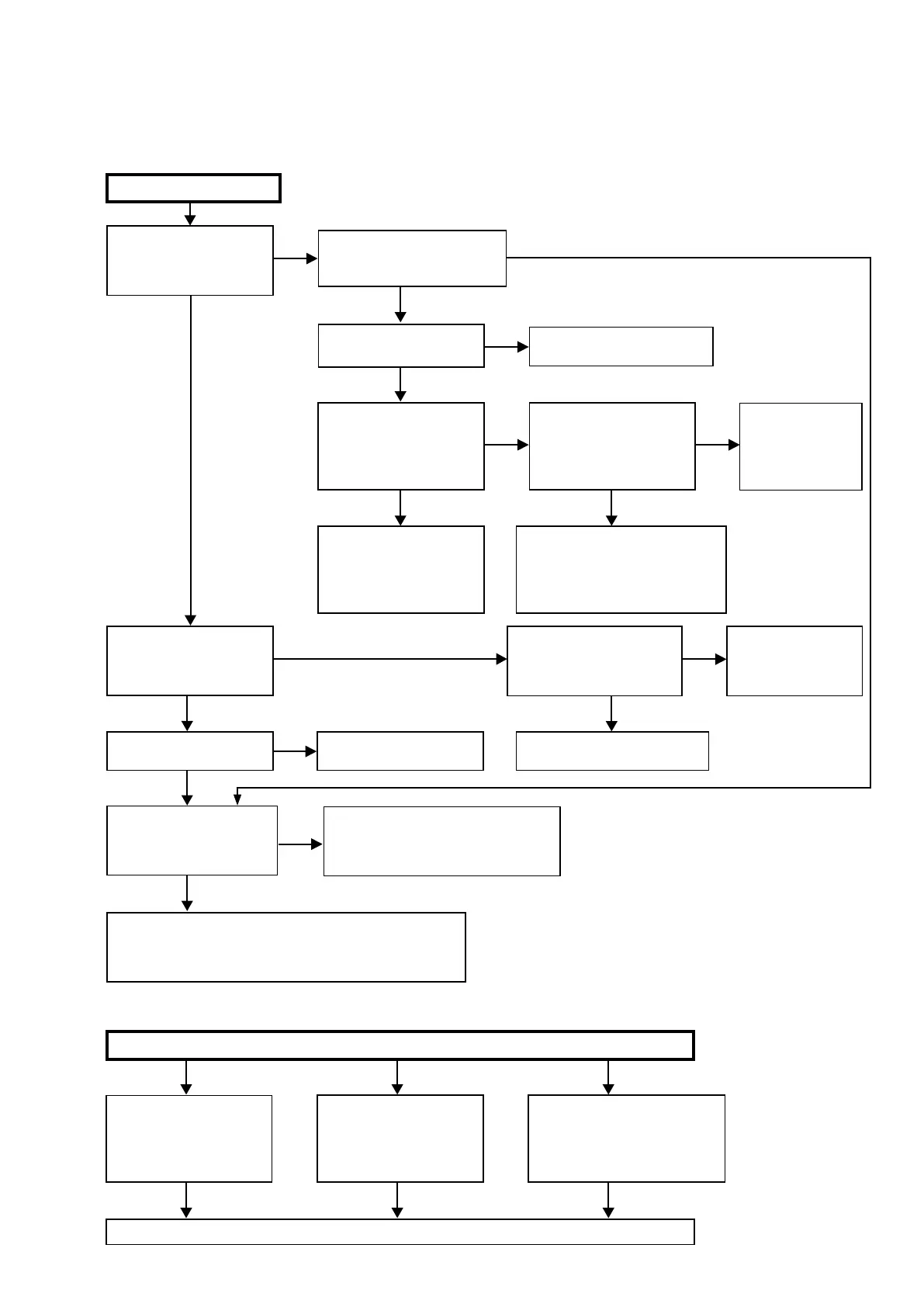
TROUBLE SHOOTING
1. POWER
1.1. The unit does not power on
YES YES
YES
NO
NO
YES
NO
NO
Does the power indicator on
the front panel ash in green
or white when the power is
turned on?
Has a fuse broken?
Does the power display on
the front panel change to
lighting in green after ap-
proximately 10 seconds?
Check the voltage of pins
7-9 of N5003 on the DIGITAL
PCB while the power display
is ashing in green or white.
Remove the connector (N6012) of the SPEAKER PCB.
Check the "
3.6. Protection history display mode
"
(See 70 page)
The unit does not power on
Has a fuse broken?
Does the power indicator on the
front panel ash in red when the
power is turned on?
Is DC5V being supplied from
the SMPS PCB (N6502) to
the DIGITAL PCB?
See "
1.2.Fuse is blown.
"
See "
1.2.Fuse is blown.
"
Check the circuits around the Micropro-
cessor on the DIGITAL PCB and replace
any faulty parts.
TO "
3.6. Protection
History Display Mode
"
(See 70 page)
Are any parts not fully con-
nected in the connectors that
connect the PCBs?
Is DC5V output even when
the connector (N1808) sup-
plying power from the SMPS
PCB to the DIGITAL PCB is
removed?
Check the circuits around
the Microprocessor on the
DIGITAL PCB and replace
any faulty parts.
Check for breakages and short
circuits in the circuits and parts
between N1808 on the DIGITAL
PCB and the microprocessor power
supply and replace any faulty parts.
Connect the connectors cor-
rectly.
TO "
6. SMPS
"
(See 112 page)
NO
YES
YES
YES
NO
NO NO
YES
Check for leaks and short
circuits in the parts on the
primary side. Replace any
faulty parts.
Broken fuse
Check the rectier diode in
the rectier circuit on the
secondary side, and check
the circuit for short circuits.
Replace any faulty parts.
Replace the fuse after repair.
Check for short circuits between
the regulator output terminal and
GND in the power supply stabili-
zation circuit. Replace faulty parts
if there is a short circuit.
1.2. Fuse is blown
99

 Loading...